Twelve structural steel building projects have earned national recognition in the 2014 Innovative Design in Engineering and Architecture with Structural Steel awards program (IDEAS2).
Conducted annually by the American Institute of Steel Construction (AISC), the IDEAS2 awards recognize outstanding achievements in engineering and architecture on steel-framed building projects throughout the U.S. The award is the highest honor bestowed on building projects by the structural steel industry in the U.S. and recognizes the importance of teamwork, coordination, and collaboration in fostering successful construction projects.
The winning projects and their respective team members were recognized during AISC's 2014 NASCC: The Steel Conference in Toronto. Each year, awards for each winning project are presented to the project team members involved in the design and construction of the structural framing system, including the owner, architect, structural engineer, general contractor, and the steel detailer, fabricator, and erector.
A panel of design and construction industry professionals identified National and Merit winners in three categories, based on total constructed value: projects less than $15 million; projects $15 million to $75 million; and projects greater than $75 million. In addition, the panel awarded a Presidential Award of Excellence in Engineering to one project for structural engineering accomplishment.
Covering an array of project types, this year's IDEAS2 winners demonstrate the flexible and effective solutions provided by structural steel on a wide variety of building projects.
Each project was judged on its use of structural steel from both an architectural and structural engineering perspective, with an emphasis on:
-
Creative solutions to the project's program requirements
-
Applications of innovative design approaches in areas such as connections, gravity systems, lateral load resisting systems, fire protection and blast
-
Aaesthetic and visual impact of the project
-
Innovative use of architecturally exposed structural steel
-
Technical or architectural advances in the use of the steel
-
Use of innovative design and construction methods
The 12 IDEAS2 winners were chosen from nearly 100 submissions received from architectural, engineering and construction firms throughout the U.S.
The 2014 award-winning projects are (photos and project descriptions courtesy AISC):
Projects Greater than $75 Million
NATIONAL AWARD
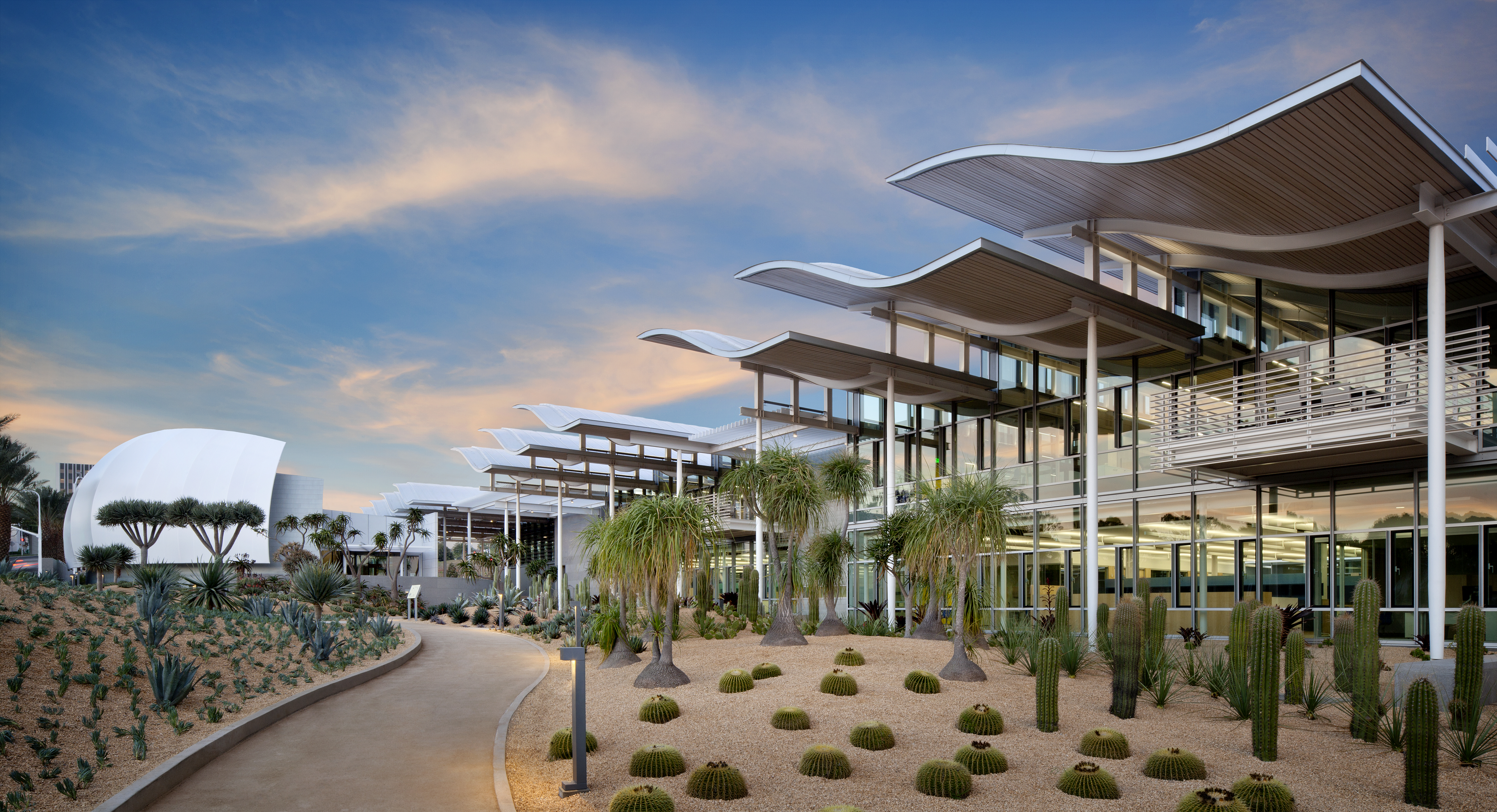
Newport Beach Civic Center and Park, Newport Beach, Calif.
Photo credit: David Wakely Photography
Building Team
Owner: City of Newport Beach, Newport Beach, Calif.
Architect: Bohlin Cywinski Jackson, San Francisco
Structural Engineer: Arup, San Francisco*
General Contractor: C.W. Driver, Irvine, Calif.
Steel Fabricators: SME Steel, West Jordan, Utah; Southwest Steel, Henderson, Nev.
*Firm that entered project in IDEAS2 contest
Standard steel wide-flange and hollow steel sections (HSS) were adapted to complement the architect’s vision while providing sustainable building features through coordinated multi-disciplinary services provided by the structural engineer. The iconic wave-shaped roof form that covers city hall and provides ample outdoor shelter was created by bending W10 sections in double curvature with multiple radii. Each wave roof perches over a Vierendeel truss crafted from W10s that allows for operable, north-facing clerestory windows and a place to nestle dimmable lighting. Penetrations in the webs of wide flanges were used for conduit and fire sprinklers.
The flexibility and control over the lighting and mechanical systems made possible by the carefully coordinated structural steel design will save the LEED Gold Certified city hall building an anticipated $85,000 a year on operating costs.
The City of Newport Beach offices are on display alongside perimeter public corridors stretching the entire length of the building and vertical circulation cores. To complement this open expression, the majority of the steel structure is proudly on display to exhibit its purpose and function. The aesthetic desire for slender vertical supports around the perimeter of the building is achieved with tapered end round HSS and a simple pin connection at the base built up from steel plates.
The buckling restrained brace (BRB) frames were made to fit the structurally required core area within the architecturally desired round HSS casing size. Exposed BRB’s with pin connections are prominently displayed at the entrance to the Community Room, in all of the repeated cores, and in private offices. The steel skeleton forms a sculpture that demonstrates to occupants how both gravity and lateral earthquake forces flow from the roof down to the foundations.
To prevent obstruction of sightlines to the Pacific Ocean, the already-sloping site was carved away so that the two story structure steps down 18 inches at every bay. This led to a stepped diaphragm at the second floor, which coupled with the discontinuous wave roof diaphragms provided a challenge of delivering diaphragm forces to the BRBs located in the cores. Diaphragm forces from each wave roof segment are collected through pinned ended round HSS collectors that double as chords. The gusset plates of these pinned collectors were structural elements highlighted by the architect by elongating the plate further into the core areas. At the steps in the second floor where the public edge of the core has very few horizontal connection points, the pedestrian bridge ramps, designed with wide-flange girders, were used as sloped funnels for diaphragm forces. The scissor stair in each core was carefully detailed with a ground floor sliding base plate to allow for the two inches of interstory drift.
The 60-ft span pair of tensioned cable trusses allows for a column-free, 150-seat space for public gathering in the council chambers during city council meetings. The unobtrusive trusses are constructed with a thin-tensioned-rod bottom chord, cruciform struts made from steel plate, and a built-up plate and back-to-back MC section top chord. The wall behind the dias bench is the formwork for the iconic sail. The curved-in-plan sail support wall is assembled out of vertically canted rectangular HSS sections and square HSS special concentric braced frames.
The existing public library was expanded to create an area for children and private reading spaces in the 17,000-sq-ft, two story, wide-flange steel moment frame addition. A café and credit union will serve the community in the new main entrance that opens up to the new Civic Green.
Tapered steel plate girders of the roof cantilever in excess of 50 feet in two directions over a single exposed steel built-up column prominently displayed at the entry doors, forming a dramatic entry canopy that thins down to a 6-in. architectural fascia.
Scattered through the 14 acres of restored wetland park are three simple profile steel pedestrian bridges and a steel girder bridge that connects two parcels of park land that are separated by a main thoroughfare. The sightline friendly, low-profile San Miguel Bridge was designed with two major wide-flange girders that span 150 feet from the abutment anchored on the north end to the elevator tower on the south parcel. The main girders fly over the top of a pair of wide-flange cantilever beams embedded in the concrete shear wall elevator tower and cantilever out to form a 52-ft observation platform that has striking views to the Catalina Islands.
MERIT AWARD
Salt Lake City Public Safety Building, Salt Lake City
Photo credit: Jeff Goldberg/Esto Photographics
Building Team
Owner: Salt Lake City Corporation, Salt Lake City
Owner’s Representative: MOCA Systems, Salt Lake City
Architects: GSBS Architects, Salt Lake City*; MWL Architects, Phoenix
Structural Engineers: Dunn Associates, Salt Lake City; Holmes Culley, San Francisco
General Contractor: Okland Construction, Salt Lake City
Steel Fabricator: SME Steel, West Jordan, Utah
Steel Detailer: SNC Engineering, Inc. Compton, Calif.
Steel Erector: SME Steel, West Jordan, Utah
*Firm that entered project in IDEAS2 contest
Public architecture articulates the aspirations of its elected governing leadership who are the voice of the electorate. Salt Lake City made a bold statement locating its new Public Safety Building as part of the Salt Lake City Civic Center where it embraces some of the best urban design and architecture in Utah. The building is an emblematic statement inviting the public to use and explore its plazas, spatially complex lobby and transparent meeting rooms to interact with police and fire administration in open dialogue and action.
The building houses the city’s police, fire and emergency management departments. The 172,000-sq-ft project was designed to achieve the city’s goals of providing an open and inviting public safety facility that will remain operational after the maximum credible earthquake (2500 year return period), provide a high level of security to its staff, and operate as a Net Zero Energy building and a sustainable site.
Key to the ultimate design solution was an iterative non-linear dynamic analysis and design procedure to arrive at a structural design capable of meeting the seismic requirements of the project within the budget. The structural system ultimately selected is comprised of a steel moment frame with viscous dampers that act like shock absorbers. All building components are designed to meet rigorous non-structural seismic standards and with redundancy allowing building equipment and systems to function after the maximum credible earthquake.
Upon selecting a system the team then proceeded with an iterative evaluation procedure to model the structure using special three-dimensional non-linear dynamic response history analyses to verify the required performance of the structure. Seven suites of site-specific scenario ground motions were used to verify the required operational performance in accordance with ASCE-41 criteria. The team was then able to deliver a structural steel frame that was designed to be capable of resisting the highest level of design seismic risk with the required high-performance objective. They also were able to provide resistance to blast by employing Side-Plate connections that ensure frame continuity and resistance to progressive collapse after a bomb attack.
The seismic/blast requirements for the building resulted in an elegant structure with SidePlate connections that present a unique challenge for the mechanical, electrical, plumbing and fire protection (MEPF) routing. The complexity of the structure coupled with the sheer volume of piping necessary to feed the buildings central plant and equipment made Building Information Modeling (BIM) an absolute necessity. BIM was implemented during the design phase to locate and design beam penetrations that would meet the strict seismic/blast requirements of the project. These penetrations were a vital component to the mechanical design. During the construction phase BIM was essential to ensure all the piping, duct and conduit would fit within the allotted space without the need to lower ceilings. Typically 14’-6” floor-to-floor would be more than adequate to fit equipment and piping; however the size of structure substantially reduced the amount of available space. By working through clashes prior to construction, the team was able to avoid costly rework in the field and as a result eliminated schedule delays. BIM was a collaborative process that required contributions from the design, contractor and subcontractor teams to find the best solution that had the least amount of impact to the final product.
Structural Engineering Accomplishments:
• Innovative use of a dual lateral force resisting system comprised of viscous dampers and a special steel moment resisting steel frame with integrated proprietary SidePlate moment connections to achieve immediate occupancy.
• Perimeter SidePlate moment frames serve the dual purpose of providing anti-terrorism force protection requirements for the prevention of blast protection and progressive collapse.
• Expressed dampers and gussets that visually promote an aura of strength and reliability for Police & Fire departments.
• Full integration of steel columns in Emergency Operations Center and the underground concrete parking structure.
The building is slated for LEED Platinum rating and is the first Net Zero public safety building in the U.S. Two structural elements elegantly express these accomplishments and contribute to the aesthetics of the building.
MERIT AWARD
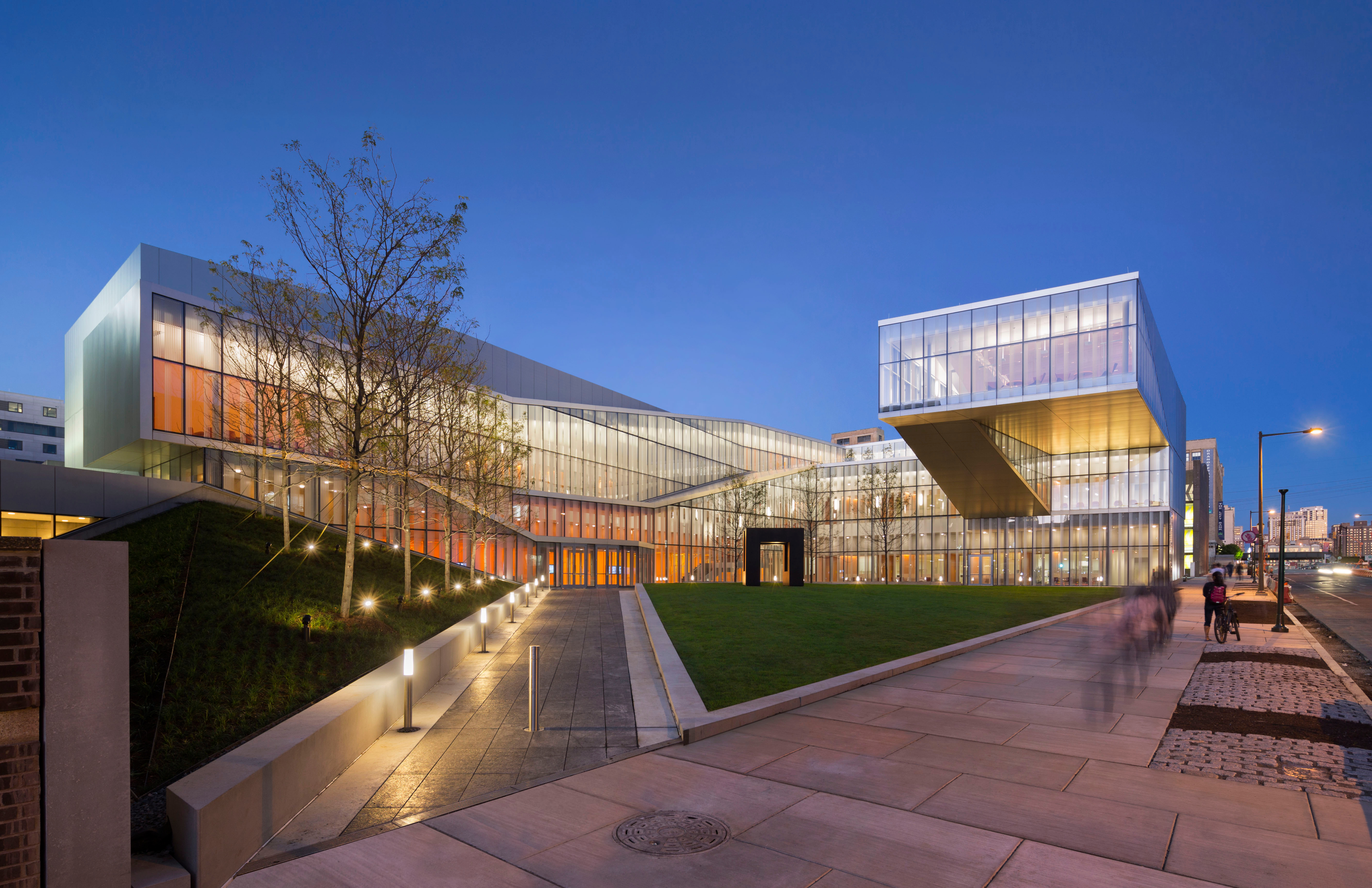
Krishna P. Singh Center for Nanotechnology, Philadelphia
Photo credit: WEISS/MANFREDI Architecture/Landscape/Urbanism
Building Team
Owner: University of Pennsylvania, Philadelphia
Architect: WEISS/MANFREDI, New York*
Structural Engineer: Severud Associates, New York
General Contractor: Gilbane, Inc., Philadelphia
Steel Fabricator: Lynchburg Steel & Specialty Company, Monroe, Va.
Steel Detailer: Delta Structural Steel Services, Idaho Falls, Idaho
Steel Erector: Steel Suppliers Erectors, Inc., Wilmington, Del.
*Firm that entered project in IDEAS2 contest
Poised at the western edge of the city of Philadelphia and the eastern edge of the University of Pennsylvania campus, the newly opened center demonstrates the university’s leadership in the emerging field of nanotechnology. Nanoscale research is at the core of cutting-edge breakthroughs that transcend disciplinary boundaries of engineering, medicine, and the sciences. As the physical and ideological convergence point of disciplines, the new $92 million dollar center contains a rigorous collection of advanced lab spaces woven together by collaborative public spaces that enable interaction between different fields. The university's first cross disciplinary building, the new nanotech research facility encourages the exchange and integration of knowledge that characterizes the study of this emerging field.
Defined by a new 1.7 acre central campus green, the 78,000-sq-ft facility ascends as a spiral of research, reaching its highest elevation at the forum, a meeting space that cantilevers 68 feet over the quad and opens to views of both the city and campus. The building contains state-of-the-art lab spaces distributed over three floors including a 10,000-sq-ft clean room lab chase for nanofabrication, a 6,500-sq-ft characterization suite, and a 12,000-sq-ft laboratory program. Connecting all four levels, the light-filled 54-ft tall galleria includes collaborative lounge spaces and conference rooms that complement research conducted within the labs.
The most sensitive nanotechnology research requires complete isolation from the surrounding elements such as vibration, electromagnetic interference, and UV light waves. In order to shape an environment suitable for these precise research conditions, the building is set back a considerable distance from the street and elevator cores of surrounding buildings. The most sensitive lab equipment is located in a secure “sweet spot” below grade to minimize vibration. The structure throughout the facility is designed to minimize vibrations through a highly efficient stabilizing structure.
The center’s most dramatic and complex structural design feature is the forum, a 4,000-sq-ft assembly space that cantilevers 68 feet over the courtyard and includes multi-purpose functions such as lectures, receptions, and meetings. Strength and vibration are core design parameters. The vibration of the floor under dynamic human loading is the controlling criteria of the structure. The vibration of the floor beams and the overall rhythmic vibration of the room are controlled by the stiffness of the trusses and lateral restraint of the braced frame. The cantilever is constructed of two inverted trusses with hang columns to capture the horizontal floor diaphragm.
The south facing curtain wall façade of the center’s galleria has a sloping roof which slices through the curtain wall plane stepping it in two directions. A horizontal truss diaphragm is employed at the sloping roof plane to resist the horizontal wind loads on the curtain wall. The north side of the horizontal truss is supported by steel columns on the foundation wall. The south side of the horizontal truss is more structurally dynamic and is supported by cantilevered beams with hanging columns which suspend the north edge of the truss from above. The hangers and columns are all architecturally exposed structural steel (AESS). In order to match the construction tolerances of the AESS, slip connections are provided where the hangers meet the upper roof steel. The lower roof between the hangers and the columns is constructed with AESS tolerances.
The monumental stair is unusual because it is a 55-ft long free-span stair stringer supported by a 24-in. deep, 20-ft. cantilever. Though deflection and strength were considerations, similar to the forum, vibration parameters controlled the design. Five 24-in. deep steel wide-flange members frame the 10-ft wide stair.
The laboratories require very strict vibration tolerances for maximum equipment performance. The lower level transmission electron microscope (TEM) rooms require a completely isolated six-sided box construction. The clean room bay and chase have 52-ft free-span beams which create a column-free space for maximum flexibility and the general labs contain 34-ft free-span beams to allow for a column-free space. This design resulted in an actual vibration criterion that exceeded the anticipated design criteria.
On the lower level of the building, due to a high groundwater table located only 8 feet below grade, a water tight concrete structural tub was required to resist the hydrostatic pressure of the groundwater. Some of the most expensive and sensitive laboratory equipment is located in the lower level where harmful vibrations are most controlled.
MERIT AWARD
U.S. Courthouse, San Diego, San Diego
Photo credit: Heliphoto
Building Team
Owner: U.S. General Services Administration, Region 9, San Francisco
Architect: Richard Meier & Partners Architects LLP, Los Angeles
Structural Engineer: Englekirk & Sabol Consulting Structural Engineers, Inc., Los Angeles*
General Contractor: Hensel Phelps Construction Co., Irvine, Calif.
Steel Fabricator: SME Steel, Jordan, Utah
Steel Erector: SME Steel, Jordan, Utah
*Firm that entered project in IDEAS2 contest
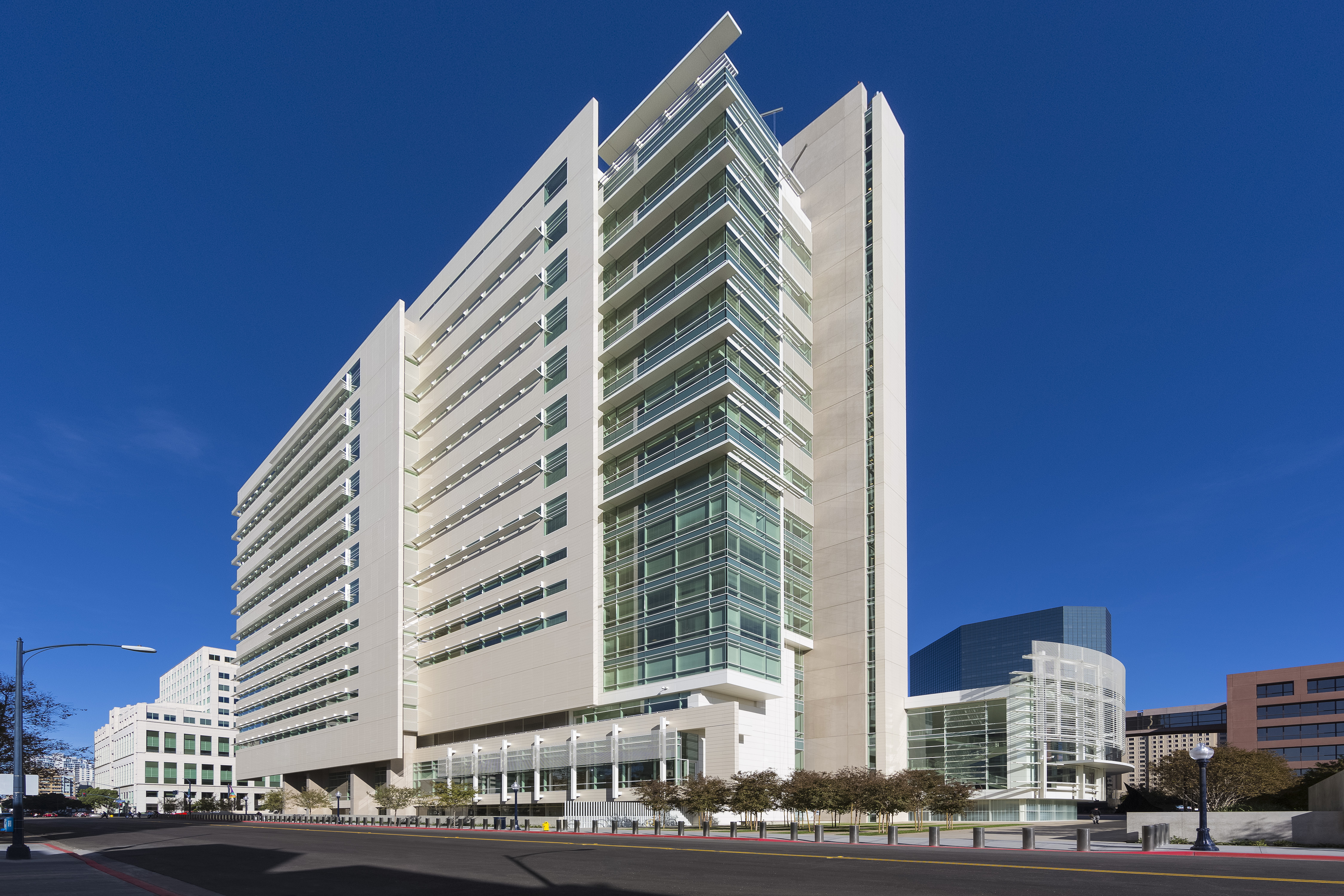
The $300 million U.S. Courthouse, San Diego, comprises 463,700-sq.- ft annex adding 14 courtrooms, chambers, general office and support space as a free-standing tower adjacent to the existing Schwartz United States Courthouse. Located at the western edge of a growing downtown San Diego, the project integrates new and existing federal buildings with gardens, plazas, a water feature, and pedestrian paths that support downtown urban design goals. To balance program requirements and civic amenities, the 100,000-sq.-ft site creatively utilizes below-grade support and service areas, while the courthouse’s plaza-level footprint is a modest 20,000-sq.-ft. This planning strategy allows the heart of the site to be developed as a significant new public plaza, serving as an active center of the federal building complex and an important new civic spac
The architectural massing of the new courthouse combines a slender 16-story tower that rises above a transparent and translucent building base. The tower is clad in wafer-like layers of terra cotta and glass composed in response to the program and orientation. The ultrathin massing supports sustainable design strategies to daylight the entire building. Adjacent to the lobby is a large jury assembly space, which opens to an outdoor jury assembly terrace with views to the plaza and gardens.
In juxtaposition to the rectilinear tower, the building lobby is an iconic elliptical volume carefully positioned to be visible from all approaches to the site. The lobby’s form serves to receive and redirect staff and visitors to the multiple courthouse destinations and is filled with filtered daylight from a south-facing two-story glass curtain wall. The lobby expresses its San Diego roots by paying homage to the locally beloved 1915 Balboa Park Botanical Building. Curved steel tubes and exposed steel framing in this new structure mirror the lath-house design employed in the original.
At the tower floors, public circulation is oriented along the glazed east elevation offering exceptional views to the plaza, city, and south bay. The two-courts-per-floor design eliminates traditional internal corridors and gives human scale to the procession from entry to courtroom. This activity is visible from the public plaza and, through the building façade, expresses a dynamic and accessible judicial process.
The palette of materials and “color” are inspired by the city itself. The warm off-whites, that turn golden at sunset, help set the Mediterranean stage that makes San Diego unique. To achieve this color, façade materials include painted structural steel, natural stone, terra cotta and concrete. Each of these materials displays qualities of strength and permanence.
Architecturally exposed structural steel is expressed prominently in the architecture, including the lobby curtain wall and screen as well as site amenities such as the trellis along the main entrance ramp. Weathering steel plate edging the accessible path between the plaza and entrance lobby boldly complements the subdued colors of the building.
High seismicity, a narrow plan contrasted with significant overall height, required column-free jury assembly areas at Level 1 and blast and progressive collapse requirements posed the primary structural challenges. These were met by working creatively with the design and construction team to develop a functional structural geometry that was validated using a performance-based design methodology to achieve a cost-effective seismic solution.
Concrete-filled metal deck supported by steel wide-flange beams and columns resist gravity loads. Open space requirements at the public level call for a relatively small number of columns, and result in typical spans on the order of 45 feet. Quiet seating in the courtrooms demands stringent floor vibration criteria, which were satisfied by carefully analyzing selected applications of framing continuity in concert with progressive collapse requirements.
Security considerations required that no essential part of the building’s resistance to catastrophic blast loads encroach beyond the blast setback zone, yet urban design goals pushed to bring the north and west building lines as close as possible to the property edge to maintain alignment with adjacent buildings. Double cantilevered girders at the northwest corner, for example, allow the building to project beyond the blast setback while protecting the lower portions of the building.
An eccentrically braced frame (EBF) provides seismic stability and offsets drift problems created by courtroom floor-to-floor heights in excess of 22 feet that made moment frames impractical. Concrete shear walls below the Plaza Level transfer lateral loads to the foundations.
At 320 feet in height, the building exceeds the 240-ft maximum for an EBF. Although some dual systems using concrete and steel do not have building code height limitations, the construction manager advised that mixing major subcontracting trades would result in cost premiums. In addition, trial designs of various dual systems suggested that moment frames would not participate cost-effectively in the overall lateral system due to their flexibility relative to other stiff elements in the dual system. The owner approved innovative performance-based design criteria developed by the structural engineer, which demonstrated that a steel EBF was an effective seismic system, saving several million dollars.
The project benefited from early retention of the CM-at-risk, which is not always possible on publicly funded projects. The team took advantage of this to reduce overall construction time by working together to carefully coordinate building systems within the tight envelope demanded by the high-ceilinged spaces, supplemented by continuous on-site coordination of shop drawings. This up-front work paid significant dividends because the project was completed a month ahead of the completion date established before construction began.
Cost efficiency demanded different foundation systems under the tower and other subterranean areas, which can lead to unacceptable differential settlements. Introducing a joint around the tower to minimize adverse consequences would have reduced construction productivity as well as proven an on-going maintenance problem. Using a detailed project schedule developed by the CM-at-risk, the structural engineer developed multi-stage structural models to investigate and discount differential settlement concerns thereby eliminating the need for a plaza-level joint.
Projects $15 Million to $75 Million
NATIONAL AWARD
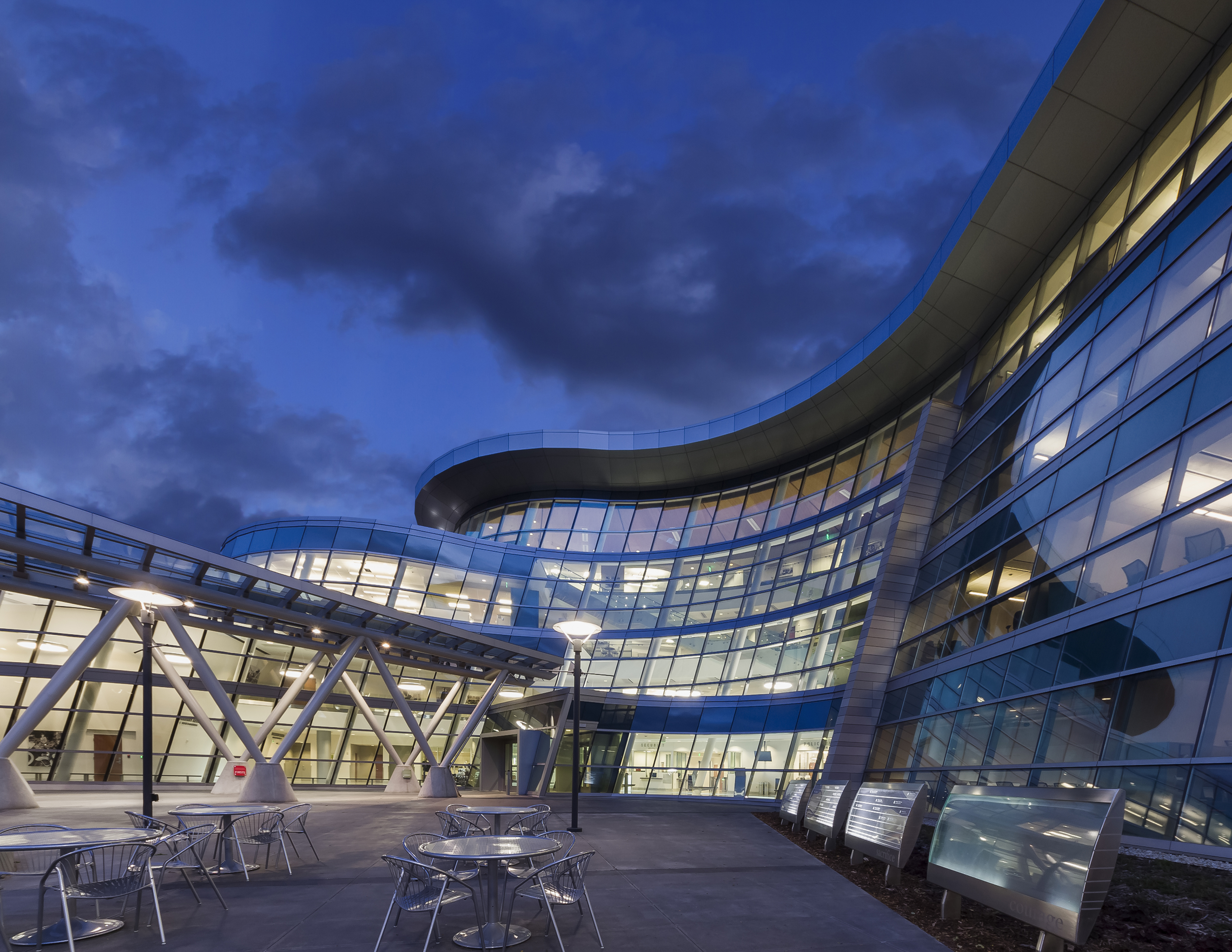
U.S. Army Corps of Engineers Federal Center South Building 1202, Seattle
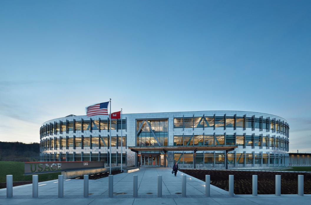 Photo: Benjamin Benschneider
Building Team
Owner: U.S. General Services Administration, Northwest/Arctic Region
Architect: ZGF Architects LLP, Seattle
Structural Engineer: KPFF Consulting Engineers, Seattle*
General Contractor: Sellen Construction, Seattle
*Firm that entered project in IDEAS2 contest
Recently completed by the U.S. General Services Administration (GSA) for the Seattle District of the U.S. Army Corps of Engineers (USACE), the Federal Center South Building 1202 transforms a 4.6?acre brownfield site into a highly flexible and sustainable 209,000-sq.-ft regional headquarters.
The building, which meets USACE’s need for a more productive and collaborative workspace, fostering teamwork and efficiency, utilized steel to creatively solve a number of specific program criteria and site challenges:
• A perimeter diagrid to defend against progressive collapse
• Architecturally exposed floor framing synchronized with mechanical, lighting, and acoustical
• Ceiling solutions
• Integrated steel and reclaimed timber floor framing in the building’s “Commons”
• Blast protection at the building envelope
• “Energy Piles”
Building 1202 is the result of responding to both the 2009 American Recovery and Reinvestment Act (ARRA), which focused on improving our nation’s infrastructure and creating jobs, and the GSA’s Design Excellence program, which establishes nationwide procedures for selecting the finest architects and integrated design teams for GSA commissions. Building 1202 was planned, designed, and constructed in less than two and a half years, and stayed within its original $68 million design and construction budget.
The design organizes functions into two distinct forms, each with their own structural system and innovative approach. Open offices take shape around an oxbow-shaped exposed steel structure and perimeter diagrid. In the central core, conference and teaming rooms are constructed of reclaimed lumber and an innovative composite wood and concrete assembly supported on steel girders. These diverse structural systems not only meet the demanding structural requirements, but are also key contributors to the overall architectural expression and performance of the project.
The building’s form pays tribute to the site; Building 1202 is located at one of the last remaining oxbows of the original Duwamish Waterway and is actually situated on fill deposited when the Corps dredged and straightened the waterway in the early 1900s.
A perimeter diagrid was employed to serve against the progressive collapse design requirement. The diagrid consists of sloping columns and spandrel beams with bolted (pinned) connections between the members that creates an efficient and inherently redundant structure.
Compared to a conventional moment frame approach for solving progressive collapse, the diagrid
system achieved economy (and used less labor) by:
• Eliminating pile foundations.
• Reducing the steel tonnage by 30%.
• Accelerating erection.
• Eliminating full penetration welds at connections between the spandrels and the columns.
• Achieving smooth transitions through the curved portions of the building, facilitated with the diagrid by utilizing a tangential variation at each floor line. This allows the exterior skin to easily transition through the corners of the U?shape, resulting in a smoother appearance. The diagrid is painted white throughout in order to assist in diffusing both natural and artificial light inside the building, but also to be prominently visible through the exterior glazing.
The diagrid is celebrated as an integral part of the building’s architectural expression as well as a physical manifestation of the Corps’ motto of “Building Strong.”
Since the steel floor framing is exposed, the layout of the steel members was synchronized with the work station sizes and the ceiling solutions for the lighting, chilled beams (mechanical system), and acoustics.
Steel girders and connection materials were integrated with an innovative composite timber?concrete beam framing system in the central “Commons.” The wood was reclaimed from a warehouse that previously occupied the site (300,000 board feet of timber was reclaimed). Steel and timber were also integrated on the stairs and pedestrian bridges.
Steel framing was used in combination with light-gauge steel to resist blast loads on the building’s perimeter envelope. The steel trusses in the atrium were also design to meet blast requirements. The building is supported by 205 steel pipe piles that extend through soft, liquefaction?prone fill and alluvial soil. The piles are 150-ft to 175 ft long, and derive support in dense glacial soil -- 135 of the piles contain ground source heat exchange loops, creating “Energy Piles” that form the backbone of a geothermal system that works in concert with the building’s high-performance mechanical systems. This is one of the first projects in the region to combine the use of geothermal heating and cooling systems with structural piles.
Extensive 3D BIM modeling was performed to identify and resolve issues between the design disciplines prior to construction. These models were merged on a weekly basis in order to check design progress, resolve clash detection issues, and facilitate design decisions. Once construction began, the model served as a common tool that field trades used for communication and issue resolution.
The structural engineer was co?located at both the architects’ offices and steel detailers’ office to fully optimize communication and coordination between the design and construction team.
On?site prefabrication was used for the exterior wall panels and other building components. The team also utilized an existing on?site warehouse to build mock?ups of the building, including the interior office space, complete with structural, mechanical, and lighting systems.
The project exceeds or meets the owner’s program and aggressive sustainability and high?performance goals. Due to costs savings resulting from collaboration and design efficiency, a number enhancements were provided, including the Energy Piles and the potential for a rooftop PV array. The building has achieved LEED Gold status and ranks in the top 1% of energy?efficient buildings in the U.S.”
MERIT AWARD
Brookfield Place Entry Pavilion, New York
Photo credit: Bess Adler/Thornton Tomasetti
Building Team
Owner: Brookfield Properties, New York
Architect: Pelli Clarke Pelli Architects, New York; Spector Group, New York
Structural Engineer: Thornton Tomasetti, New York*
General Contractor: Plaza Construction, New York
*Firm that entered project in IDEAS2 contest
In the fall of 2013, the World Financial Center was renamed Brookfield Place as part of Brookfield Properties’ $250 million renovation to improve and expand the retail and public spaces for this unique waterfront complex. The centerpiece for this renovation is a new entry pavilion. The glass and steel pavilion will serve as the connector between the underground pedestrian passageway from the World Trade Center and Fulton Street transportation hubs to Brookfield Place and the Hudson River to the west.
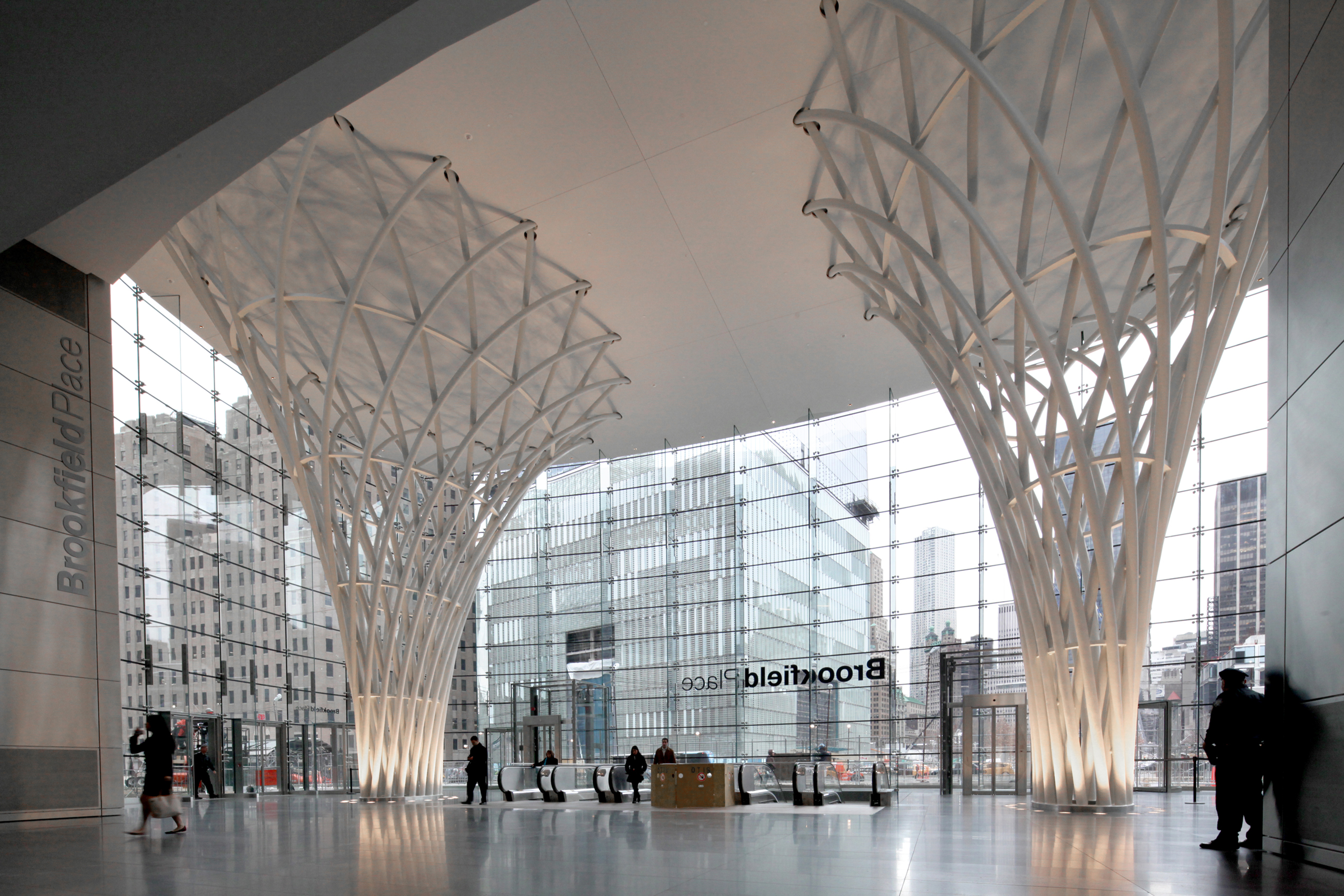
The new entry pavilion was conceived as a clear glass box with minimal structural supports, acting as the new front door for the entire complex and making its public spaces and offices more accessible to pedestrian traffic. Central to the structural and architectural integrity of the pavilion are two 53-foot sculptural steel columns which support the 8,000-sq.-ft space.
The shape of the columns and their placement within the pavilion were influenced by complex site constraints. Located above the new passageway tunnel, an existing train tunnel relieving platform, and a former pedestrian bridge pile cap, the supports for the entire structure had to be focused to only two points of contact underground. These constraints guided the design team towards the idea of two funnel shaped columns which grow from small footprints at the foundation to support the large roof area overhead.
The architect’s vision for the sculptural columns consisted of continuous pipes woven together in a basket-like fashion. Unlike typical diagrid structures where members are in a common plane and intersect at joints, the pipes for the sculptural columns were arranged in two separate layers and passed uninterrupted at each joint location. At each of the five vertical tiers, the pipes were held together by a continuous elliptical steel ring plate, and at intersections between each tier a hidden solid steel pin was used to connect the inner and outer pipes.
The structural system for the pavilion is independent from the adjacent steel and concrete superstructure of the main building. The two sculptural columns work together with deep beams concealed within the roof to support the weight of the hung glass façade while also providing the entire lateral resistance for wind and seismic loads. In one direction, the deep beams tie the two sculptural columns together to act as a moment frame, while in the other direction the columns act as cantilevers to resist overturning.
Starting from the early phases of design, the structural engineer collaborated closely with the architect and steel subcontractor to develop connection details that were capable of transferring high structural loads while also maintaining tight erection tolerances for architecturally exposed structural steel and achieving a seamless finished appearance. The structural engineer rationalized the complex curved geometry of the double-layer diagrids into individual pipe segments with constant curvature to meet fabrication requirements, and collaborated with the steel subcontractor on a welded pipe splice detail with temporary clamps that allowed adjacent sculptural column tiers to be shop assembled for fit-up and later reassembled on site in precise alignment.
All exposed welds were ground smooth and flush to provide a high-quality finish, and full size mock-ups of various joint conditions were made to allow the owner and architect to evaluate the appearance of key details.
Only through careful multidisciplinary collaboration was it possible to achieve the signature interwoven sculptural columns of the entry pavilion, gracefully flaring outward like the branches of a tree as they rise to support the virtually invisible glass enclosure of this unique space.
MERIT AWARD
Onondaga Community College, Ferrante Hall Academic II Addition, Syracuse, N.Y.
Photo credit: Tim Wilkes
Building Team
Owner: Onondaga Community College, Syracuse, N.Y.
Architects: CannonDesign, New York*; C&S Companies, Syracuse, N.Y.
Structural Engineer: CannonDesign, Grand Island, N.Y.*
General Contractor: Hueber-Breuer Construction Co., Inc., Syracuse, N.Y.
Steel Fabricator: Raulli & Sons, Inc., Syracuse, N.Y.
Steel Detailer: JCM & Associates Limited, Canada; Raulli & Sons, Inc., Syracuse, N.Y.
Steel Erector: Raulli & Sons, Inc. Syracuse, N.Y.
*Firm that entered project in IDEAS2 contest
The 45,000-sq.-ft Ferrante Hall Academic II connects two facilities, a classroom building and student center on Onondaga Community College’s campus in Syracuse, N.Y., making use of otherwise unusable land – land divided by a 60-ft deep gorge. The two-story addition affirms the college’s commitment to growing its arts programs, cultivating its music curricula and enhancing the cultural environment both on campus and in the community.
Conceived as a teaching facility with outreach to community organizations in need of performance venues, the new building encourages an integrative approach to music by providing facilities for the entire music school, including administration, production, teaching, research and support spaces. Features include a 150-seat music recital hall with 9000-sq.-ft stage and chorus balcony, a music resource center, a 2,500-sq.-ft instrumental and choral rehearsal room seating up to 110 musicians, a 1,200-sq.-ft percussion rehearsal room, practice rooms of various sizes, 16 faculty teaching offices and eight music-oriented smart classrooms.
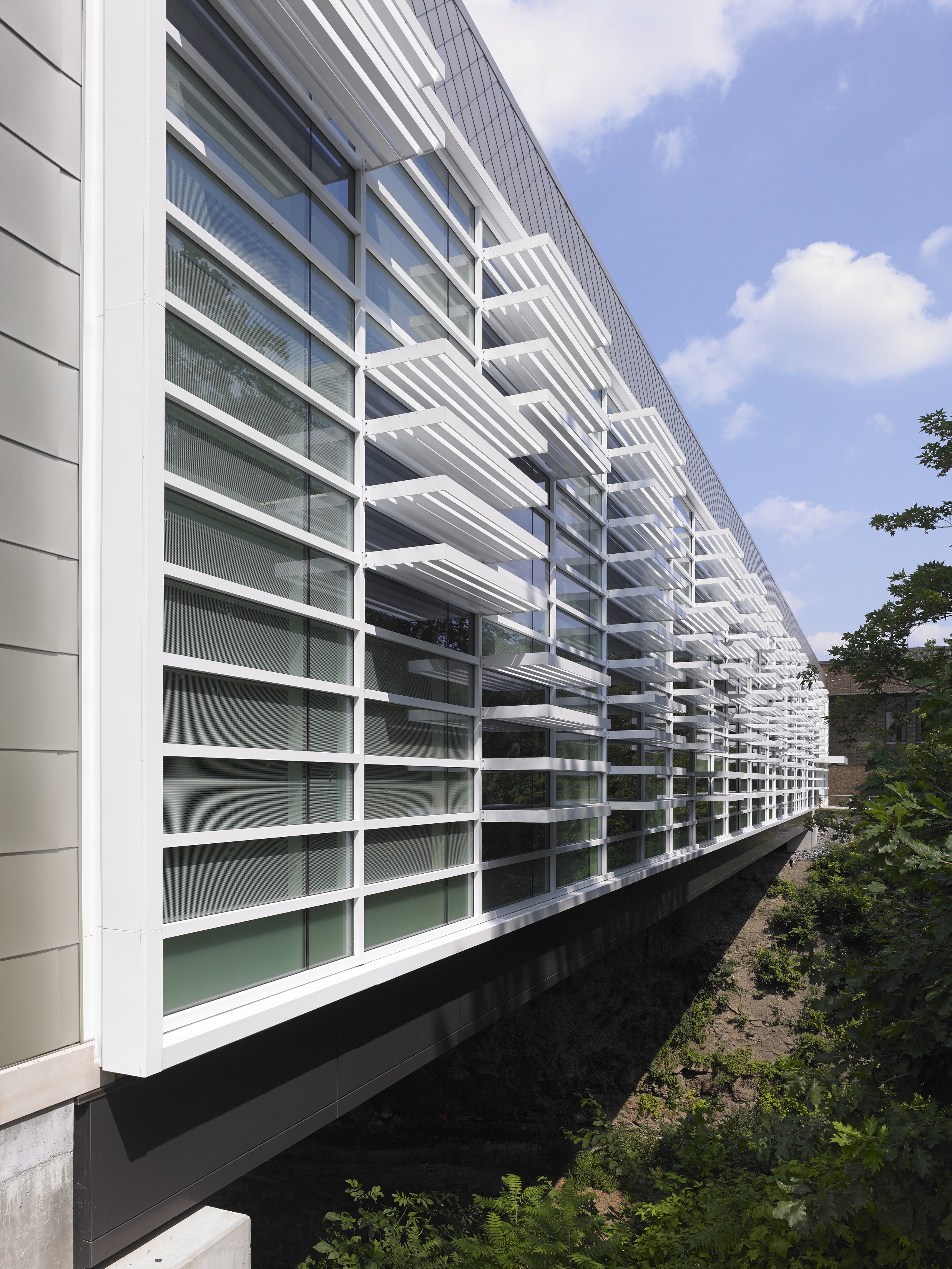
Physically connected to both a classroom building and the student center, the 45,000-sq.-ft, two-story Academic II “bridge building” unites the east and west campuses divided by the gorge, a 60-ft-deep fissure dividing the campus previously spanned only by a bridge open to the elements. It connects the campus spine on the south with public, staff and student parking to the north. The building also shares the student center’s loading dock and other support functions.
Use of bridge construction materials and techniques was essential in achieving the architectural vision. Three two-story, 200-ft trusses supporting the building incorporated some of the largest rolled-steel elements available. Structural steel elements and connections are embraced in the architectural space design. Bridge bearings are used to transfer loads to the building’s foundations.
The building’s 200-ft span relies on three 30-ft-high trusses that, due to limited working space on both sides, were erected with the help of a support tower built in the middle of the gorge, allowing trusses to be erected in two halves and spliced in the middle. This piecewise approach allowed field assembly of the trusses to occur in a smaller area and enabled use of a smaller crane.
Designers were challenged to create a structure stiff enough to span 200 feet without observable deflection or vibration, as well as address uneven loading issues due to different program requirements. Deflection also posed another, more general, challenge: If trusses were loaded after placement of curtainwall or exposed concrete floors, the deflection of the trusses could cause windows to pop out and the concrete to crack excessively. A combination of two options was used to solve the deflection issue. The trusses were preloaded to neutralize deflections and unloaded sequentially as the building was completed, and non-deflection-critical items were installed first to help deflect the trusses.
Because the recital hall was a two-story space on one end of the building, and the rest of the building was composed of two one-story layers, the load on the structure was unbalanced. While the north truss supported the weight of the roof and two lower levels, the south truss only supported a roof and one lower level, and the center truss supported a two-story space on one side and two one-story spaces on the other. To ensure compatible deflection, each truss was designed relative to the stiffness of the others as well as to its specific loading conditions.
When unexpected rock fragmentation was discovered on one side of the gorge during excavation, drilled micropiles and rock anchors were installed by a specialty contractor to supplement the building’s original 7-ft-diameter caissons.
The unusually large steel members posed another issue regarding bolt installation. During steel fabrication, the team learned that the 1 1/2" A490 bolts specified in the design had a tendency to fail if they were installed by turning the head end of the bolt instead of the nut end. In the building’s design, however, the bolts were an architectural feature specifically designed to be installed in one direction, requiring rotation of the bolt head, and because the bolts were so large they couldn't be installed any other way. This installation proceeded under careful examination with successful results.
MERIT AWARD
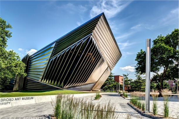
Eli and Edythe Broad Art Museum, East Lansing, Mich.
Photo credit: Justin Maconochie
Building Team
Owner: Michigan State University, East Lansing, Mich.
Owner’s Representative: Eli & Edythe Broad Art Museum, East Lansing, Mich.
Architects: Integrated Design Solutions, Troy, Mich.; Zaha Hadid Architects, London, U.K.
Structural Engineer: AKT, London, U.K.; SDI Structures, Ann Arbor, Mich.*
General Contractor: Barton Malow, Southfield, Mich.
*Firm that entered project in IDEAS2 contest
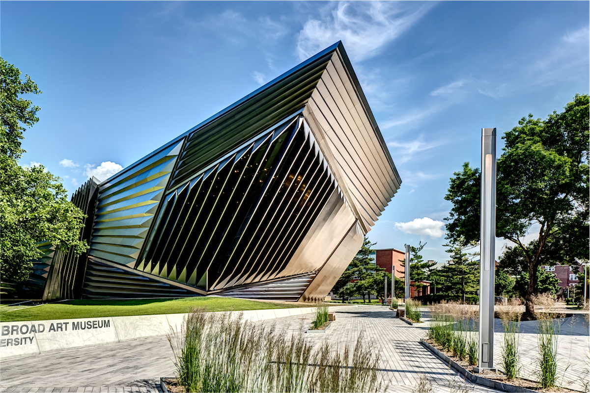
Philanthropist and art collector Eli Broad envisioned this new museum at Michigan State University as a world-class venue for the display of modern art, to be designed by the world-class, visionary London architect. To the architect who conceives the vision, the benefactor who champions it, and the owner who endeavors to see it come to life, exacting execution of that vision is of paramount importance. The vision is more than just volume, surfaces, and forms; it’s also gesture, expression and intent. So it’s not enough to merely bring physicality to the imagined form, it needs to be done in a way that preserves the spirit in which the design was conceived.
Thus, the engineering of the museum became an exercise in communicating with the architect about exceedingly complex geometry in a most nuanced way; communication that took place across three Building Information Modeling (BIM) software platforms: Rhino, Revit and Tekla. As the project developed it became evident that because of the complex geometry the most challenging phase of communication would be encountered during the production of steel shop drawings.
For this reason, the engineer of record (EOR) advocated moving away from the traditional shop drawing whereby the EOR would have the shop drawings prepared in Tekla concurrently with construction documents. Steel bidders then had the opportunity to bid the project and also to bid for use of the shop drawings, which provided confidence to the owner by ensuring that a fair price was being paid for the shop drawings that the design team had prepared. As the Tekla-based shop drawings developed, the model was continually checked against the architect’s Rhino and Revit models so that when steel bidding occurred, the shop drawings were essentially already checked for every aspect of conformance with the architect’s still-developing details. With glazing being hundreds of unique shapes shipped from Germany, and the stainless steel skin being many more hundreds of individually fabricated forms, the tolerances for construction were extremely tight. The careful BIM coordination allowed each piece to come together in a precise way.
The building frame is made up of a series of non-parallel sloping walls that interface with architectural concrete walls that are also non-parallel and sloping. Wide flange with gussets in the plane of the flange are used frequently, as are castellated beams. The stairs are Hollow Structural Section (HSS) tube frames encased in architectural metal handrails. They cantilever off of the floor slabs and return without landing supports. HSS tubes also serve as window mullions.
Projects Less Than $15 Million
NATIONAL AWARD
San Diego Main Public Library Dome, San Diego
Photo credit: Rob Quigley
Building Team
Owner: City of San Diego Main Library, San Diego
Architects: Rob Wellington Quigley Architects, San Diego; Tucker Sadler, San Diego
Structural Engineer: Endrestudio, Emeryville, Calif.*
General Contractor: Turner Construction, San Diego
Steel Fabricator: SME Steel, West Jordan, Utah
Steel Erector: SME Steel, West Jordan, Utah
Steel Detailer: SME Steel, West Jordan, Utah
*Firm that entered project in IDEAS2 contest
The 140-ft diameter post-tensioned steel-leaved dome serves as the beacon for San Diego’s 10-story, $185 million downtown main library. Conceptual designs of the dome spanned eight years and explored six differ¬ent circumferential and segmented options. The final scheme resulted in eight intersecting post-tensioned, 3D, moon-shaped truss elements with a saddle-shaped cable net on each. Adjacent to the dome, the vertical stair tower forms a strong structural core that anchors the two wings of the building. Thrusting outward and upward from this anchor are projecting triangulated arms that catch a few of the dome rib bases. The computer model of the dome enlisted over 6,000 “tension only” members and required programs written specifically for post-procesing filtering.
A special events assembly hall tops this rectilinear cluster with a stunning 30-ft high glass wall that cants out from the building’s exterior. Behind this glazing, and following its angle, is a single massive concrete column supporting two pre-cast torsional grand beams in the roof structure. Horizontal cantilevering steel triangle vierendeel trusses project from this column, holding back the tipped glass wall. This structure defines two rectangular roofs separated by a central strip of glass that illuminates the special events hall below.
The dome, believed to be the largest steel post-tensioned segmental dome in the world, is 140 feet in diameter and rises 221 feet above ground level to provide shade and acclimatize the reading room. It is constructed of more than 3,000 individual members of steel, weighing 285 tons, and clad in 1,500 perforated aluminum panels to shade the eighth floor reading room beneath it. The dome is made up of eight unique truss “ribs” that rise from base to apex in varying heights from 72 to 113 feet and eight unique “sail” structures located between the ribs.
Sails are oriented in plan with a pinwheel configuration, an effect created by offsetting each of the sails’ vertical leading edges to the outside of the ribs while the sails’ trailing vertical edges are connected to the inside rib surfaces. Each of the sails has an external pipe grid that is spherical at the upper part of the dome; however, the spheres are tipped vertically and horizontally so the center of each sail does not coincide with the center of the dome. Unfurled, the largest sail is 123 ft by 53 ft wide and comprised of 175 members of tubular steel and 60 cable segments.
Architecturally, the lower edges of the sails are desired to be as thin as possible. This is achieved through the use of a three-dimensional truss spanning diagonally from rib to rib, and appears visually as a 6-in. edge thickness. To further reduce the mass of the sails, steel cables are introduced to minimize large members on the interior surfaces close to the glass of the reading room. The penultimate concept, with cables covering the outer and inner surface, was deemed too difficult to erect by the contractor. The final design, a saddle shaped cable net, was chosen because the removal of cables on the outer surface allowed the contractor to erect them by crane more easily. The sails were constructed on-site, two at a time, on large temporary platforms on the ground and lifted into place, one sail at a time.
Due to the discontinuous circular form and its peaked pinnacle, the dome behaves as a series of intersecting three-hinged arches, or “ribs”. At the base, each rib is supported on a large fixed pin that allows the rib struc¬tures to pivot or expand with changes in temperature or seismicity. Each of the eight large pins falls onto one corner of a fixed octagonal plan. The octagonal plan causes unequal geometry from rib to rib. The fixed pins of the rib supports fall onto varying elevations located atop shear walls, freestanding columns and, in one case, supported by three inclined converging columns. Two of the rib supports fall outside the building envelope and are built on special composite braces made up of concrete columns with tubular steel diagonals.
MERIT AWARD
Battle Creek Area Mathematics and Science Center, Battle Creek, Mich.
Photo credit: Justin Maconochie
Building Team
Owner: Battle Creek Public Schools, Battle Creek, Mich.
Architect: Tower Pinkster, Grand Rapids, Mich.*
Structural Engineer: Teton Designs, Grand Rapids, Mich.
General Contractor: Schweitzer Inc., Battle Creek, Mich.
Steel Fabricator: Steel Supply & Engineering, Grand Rapids, Mich.
Steel Detailer: Steel Supply & Engineering, Grand Rapids, Mich.
*Firm that entered project in IDEAS2 contest
Students and teachers embrace the math and science center’s mantra of “Innovation Through Inspiration.” Unlike other math and science institutions, the center serves dual functions: education for exceptionally talented high-school students from 16 neighboring school districts, and the design, manufacturing and distribution of science curriculum materials.
In 2013, the center’s new home -- an $11 million adaptive reuse facility (a former cereal museum donated by the Kellogg Company) – was completed, housing the learning center and a separate distribution center.
The design team was charged with achieving the new program while transforming the agrarian aesthetic of a museum dedicated to the invention of corn flakes into a cutting-edge, 64,000-sq.-ft learning facility. The concept removed six existing barn roof forms and created cantilevered second and third floor additions over the entry plaza. Fortunately, the original building was structural steel column and beam construction that allowed the architects the opportunity to achieve all of the center’s goals. A new expressive “V” column support was added at the building’s entry to be support the new floors and be a source of inspiration for students at the entry. Glass curtainwall envelops the exterior of the second floor and allows a greenhouse at the corner, floating over the entry and showcasing the center’s commitment to research-based learning. The new third floor is shrouded in two-tone steel panels in a pattern inspired by mathematical patterns.
The interior design concept draws on biological science where walls are an expression of organic form set in motion by a three-story pendulum swinging inside the central stair. On the third floor, the pendulum is hung from a severed cone of structural steel so that students may see its inner workings. While both of the stairs’ landings are cantilevered into space, the higher one is a longer cantilever and particular source of inspiration. The structural engineer designed a steel cable support to take the bounce out of the landing, which invites students to touch and wonder about the physics of steel.
Classrooms are bounded by monolithic walls with entries created by a serpentine structural glass weaving around a three-story atrium. This Collaboration Space is phenomenally connected by new elliptical holes cut between floors and bounded by steel cable-rails. It is filled with museum-like places for study, collaboration and reflection, including a building-system display case. Scientific installations including sustainability monitors tied to building systems, suspended molecular models, interactive technology exhibits, and the students’ solar car project further enhance the space. The third floor physics lab includes a steel-cantilevered perch to drop objects from and measure results through space.
The site is situated on 600 feet of historic Battle Creek riverfront and a public park. The building acts as a visual anchor to north edge of historic Battle Creek. There is a riverfront bike path directly to Battle Creek High school, which is three blocks away. Additional exterior spaces were developed to provide safe access to the river for biology students to study, sample, and analyze the ecosystem. Proximity to the Kellogg Corporation headquarters also is a wonderful site consideration. Food science engineers from Kellogg will be able to cross a bridge directly to the center to make presentations, meet with students, and tour them through Kellogg’s real world lab environments. Other nearby business and industry partners also will frequent the center.
MERIT AWARD
United Therapeutics Pedestrian Connector, Silver Spring, Md.
Photo credit: Ron Blunt
Building Team
Owner: United Therapeutics Corp., Silver Spring, Md.
Owner’s Representative: Stranix Associates, Vienna, Va.
Architect: EwingCole, Inc., Philadelphia
Structural Engineer: EwingCole, Inc., Philadelphia
General Contractor: DPR Construction, Inc., Falls Church, Va.
Steel Fabricator: Manufab, Inc., Bay St. Louis, Miss.
Steel Detailer: Cartee-Berry & Associates, LLC, Florence, S.C.
Steel Erector: Baltimore Steel Erectors, White Marsh, Md.
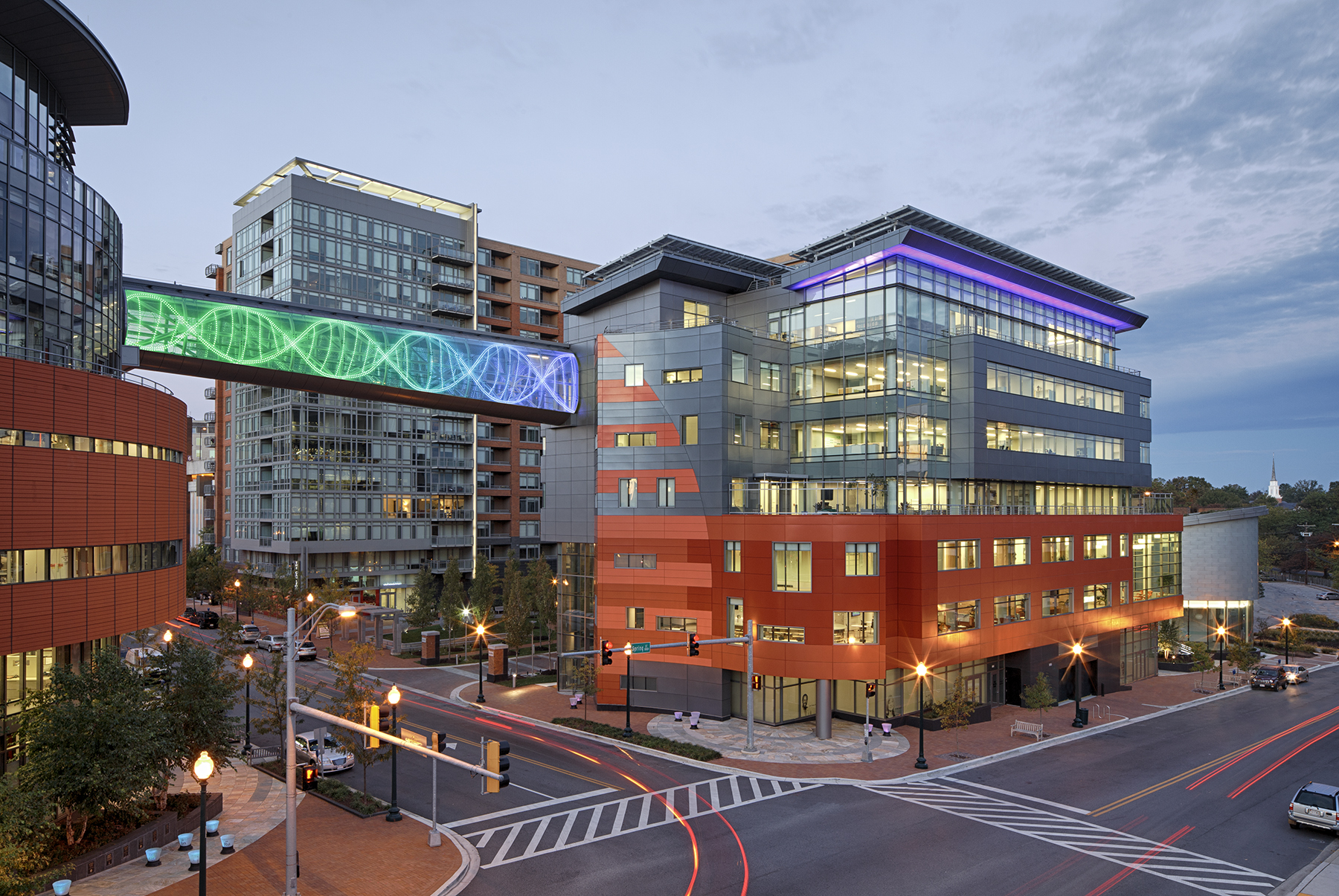
United Therapeutics campus in downtown Silver Spring, Md., includes multiple buildings within close proximity to one another in a mixed?use urban setting. The architecture and engineering firm was hired to design a new eight?story, 100,000-sq.-ft office building to support the company’s existing laboratory and corporate headquarter functions. Due to site constraints, the new facility is separated from the core campus by a busy county street. The design team proposed an enclosed skywalk – the connector – to link both sites.
Completed in 2012, the $2 million connector spans more than 90 feet across the street and connects to the sixth floor of each structure, allowing unencumbered access to new conference rooms, dining and office areas. Architecturally, the initial design concept for the connector included a glass clad circular cross?section that increases in depth as the floor slopes to accommodate a 4?ft elevation change between the two buildings, while the top of the connector remains flat. As the project progressed, the full cross section of the connector was developed as a truss, with the walking path “floating within it”. This approach created a visually stimulating pedestrian experience as they travel through the exposed, curving structural members, while maximizing the structural efficiency of the connector.
Comprised of exposed 7-in. round Hollow Structural Section (HSS) members, the truss includes 11 HSS rings that follow the extended circular cross section of the connector and are spaced at 9-ft centers. Each ring includes two half circular sections (top and bottom), with a 5-ft radius, separated by straight sections of varying length to match the slope of the floor slab. The rings are connected with eight HSS longitudinal chords that are located at the top most and bottom most point of the connector, at mid-height of the sides and at 45 degrees from each spring point of the top and bottom arched sections. HSS diagonals frame between node points created at the ring/chord intersections and follow the curvature of the ring members between nodes resulting in diagonals that curve in two planes.
The connector was designed to support a 100-psf occupant load on the walking deck, a 40-psf catwalk live load, loads due to snow, ice, wind, seismic, and OSHA safety loads for glass cleaning. AISC Design Guide 24 and AISC 360?05 Chapter K were used to check all limit states of HSS members due to localized effects of HSS round member connections. Welds were checked for the combined effects of bending and axial member end forces. Deflection and vibration serviceability requirements were carefully evaluated and an expansion joint with a slide bearing connection was introduced at the one end of the connector to account for differential building movements due to thermal expansion and contraction and lateral loading conditions.
The fabrication of the 28?ton connector required careful planning with as many as eight round members joined together at a single node, six of which are curving. The round HSS members required elliptical end cuts of curved members that were then chamfered to accommodate varying dihedral angles for partial penetration welds. Qualification of welding procedures was required for round HSS partial penetration “K” connections that did not meet the geometry requirements for prequalified AWS welded joint designations. Qualification testing included transverse cutting of welded joint mockups and macroetch testing of the weld cross sections.
Through close collaboration with the fabricator, the structural engineer suggested a staggered fabrication sequence that allowed assembly of the connector without cutting the diagonal members and eliminated 80 full penetration welds.
Prior to fabrication, the attachment points to each building were surveyed to ensure that the connector would fit between the two buildings. The connector was fabricated in one piece and shipped by truck from Mississippi. The connector was erected in one lift by a single crane with only 3 inches of clearance to the existing concrete structures at each end of the connector.
Completed in 2012, the new building and connector earned LEED Gold Certification from the U.S. Green Building Council. Computer controlled LED lighting traces the symbolic pattern of a DNA strand and reinforces the biotechnology focus of United Therapeutics.
Presidential Award of Excellence in Engineering
One World Trade Center, New York
Photo credit: Yoram Eilon, courtesy of WSP
Building Team
Owner: The Port Authority of New York and New Jersey, New York
Owner’s Representative: STV, New York
Architect: Skidmore Owings and Merrill, New York
Structural Engineer: WSP, New York*
General Contractor: Tishman Construction, New York
*Firm that entered project in IDEAS2 contest
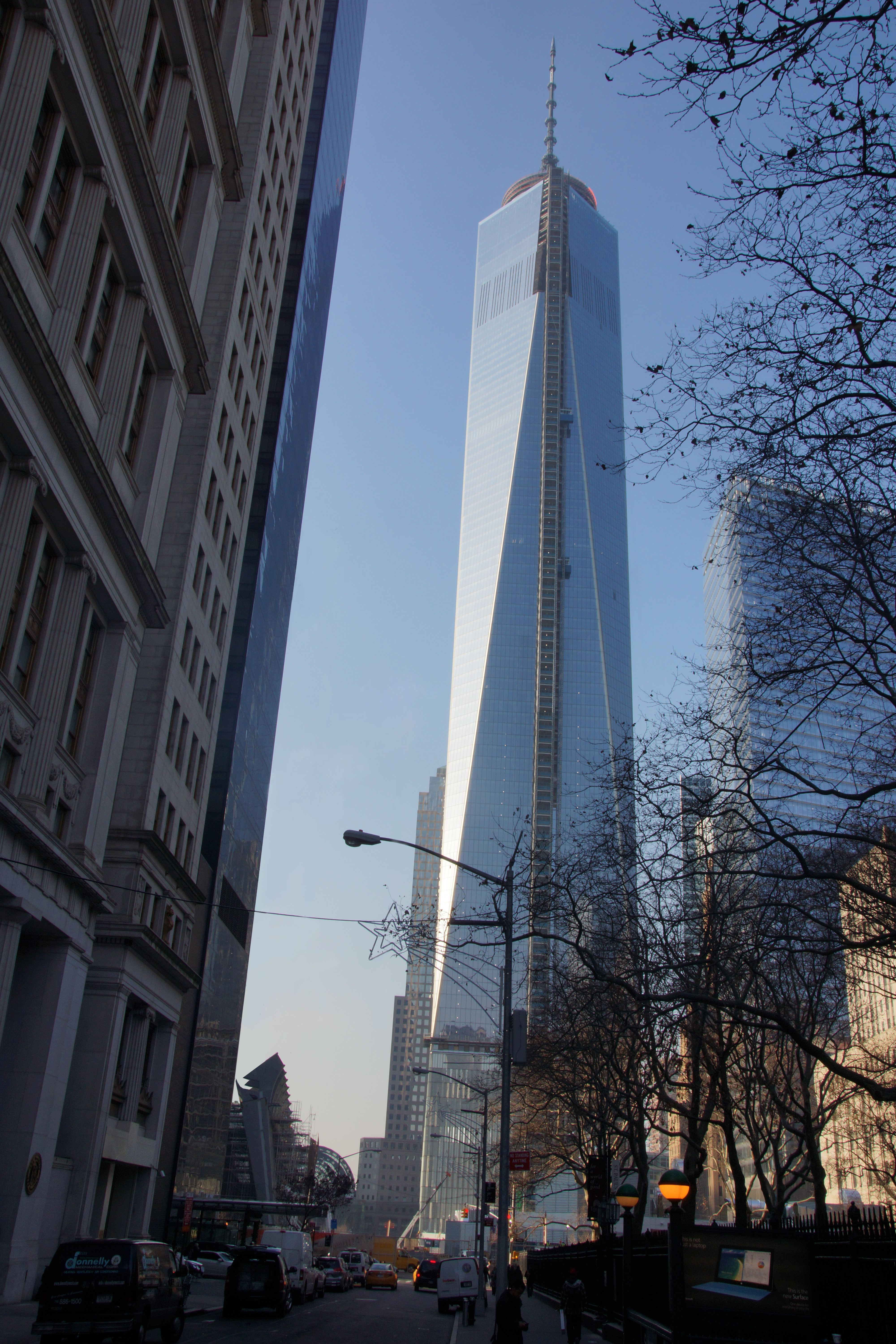
One World Trade Center (1WTC) is the tallest of the four buildings planned as part of the Ground Zero reconstruction master plan for lower Manhattan. It is the tallest building in the Western Hemisphere with an overall height of the tower from ground level to the top of the spire reaching 1,776 feet. At 1,368 feet above ground, the main roof is designed to be the same height as the original towers.
With security paramount among the numerous and unique challenges faced by the design team, specific technical solutions and details remain confidential.
The project’s program includes 3 million sq. ft of new construction above ground and 500,000 sq. ft at new subterranean levels. The tower consists of 71 levels of office space and eight levels of MEP space. It also contains a 50-ft high lobby, tenant amenity spaces, a two-level observation deck at 1,242 feet above ground, a sky restaurant, parking, retail space and access to public transportation networks.
The tower structure is comprised of a hybrid system combining a robust concrete core with a perimeter ductile steel moment frame. The reinforced concrete core wall system at the center of the tower acts as the main spine of the tower providing support for gravitational loads as well as resistance to wind and seismic forces. It houses mechanical rooms and all means of egress. The core structure is compartmentalized with additional internal shear walls in orthogonal directions.
A ductile perimeter moment frame system is introduced for redundancy and to further enhance the overall building performance under lateral wind and seismic loads. The perimeter moment frame wraps around all vertical and sloped perimeters forming a tube system.
The tapering of the building geometry reduces the wind effect on the tower. Generally, tall-building design in New York is governed by wind load. However, this tower shape has an innate positive effect on the building performance under the wind loading. Along the height of the tower, the tapering multifaceted geometry creates unique structural conditions which necessitated the design and fabrication of special nodal elements using relatively large plating with significant capacity for load transfer.
For further enhancement of the lateral load resisting system, the concrete core at the upper mechanical levels is connected to the perimeter columns via a series of multilevel outrigger trusses in both orthogonal directions.
While the floor system within the concrete core zone is cast-in-place concrete beam, the floor area outside the core is concrete on composite metal deck supported on steel beams and connected via shear connectors acting as a composite system. At 1WTC, the construction was sequenced by first erecting an all-steel framing system throughout the floor, both inside and outside the core, preceding the concrete core construction. The steel framing within the core is primarily an erection system which is embedded in the concrete core walls.
The tower structure extends 70 ft below grade passing through four subterranean levels where some of its structural components required repositioning to clear the Path train tracks that pass beneath the building at the lowest basement level. The tower foundation is founded on Manhattan rock using spread and strip footings with bearing capacities of 60 tons per sq. ft or better. At selected locations, due to space constraints such as the proximity of the existing operating train lines, it was necessary to excavate deeper into the rock to achieve a higher bearing capacity.


