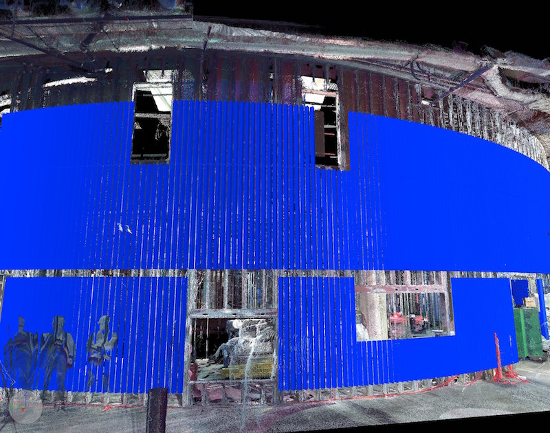
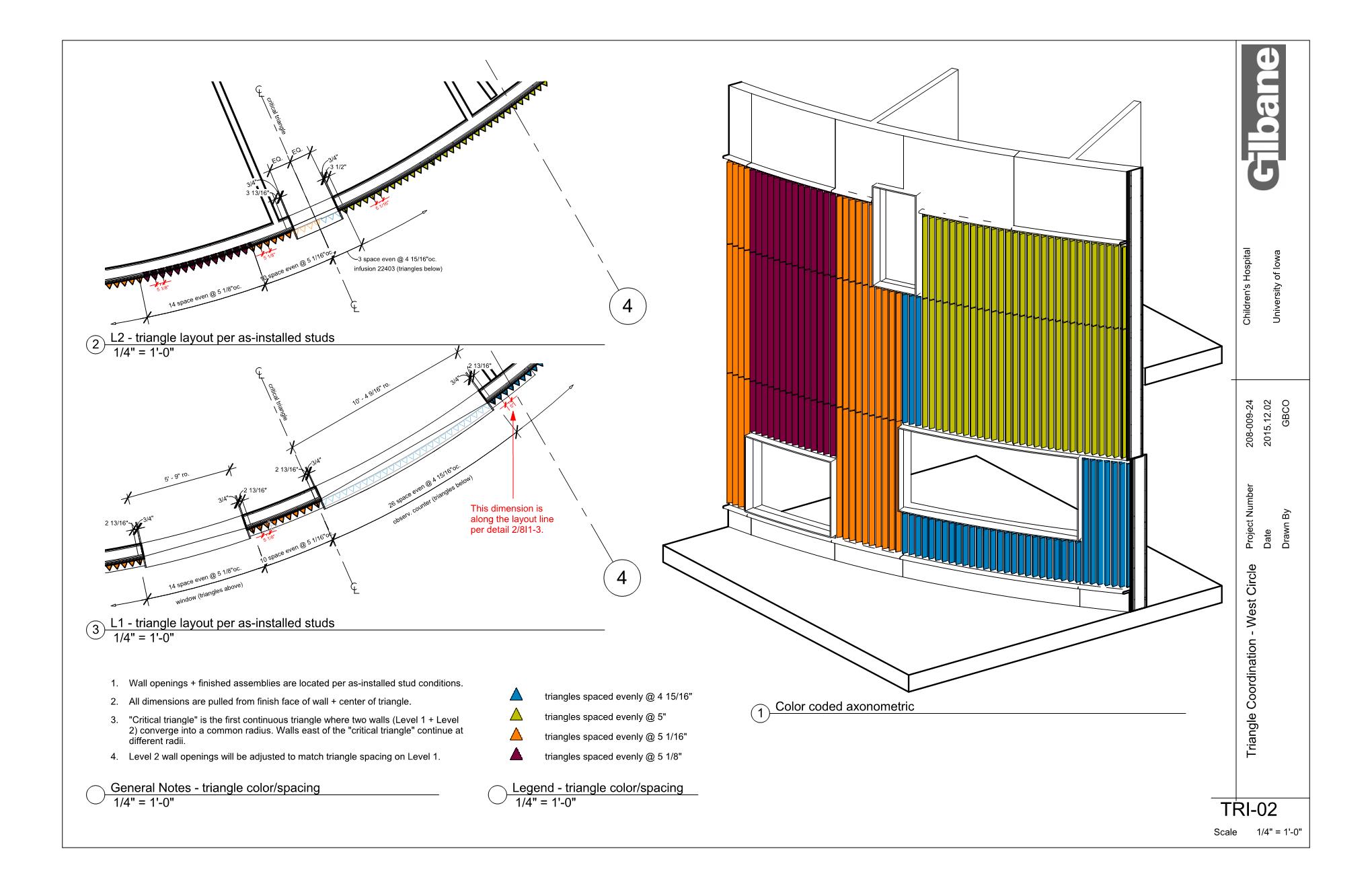
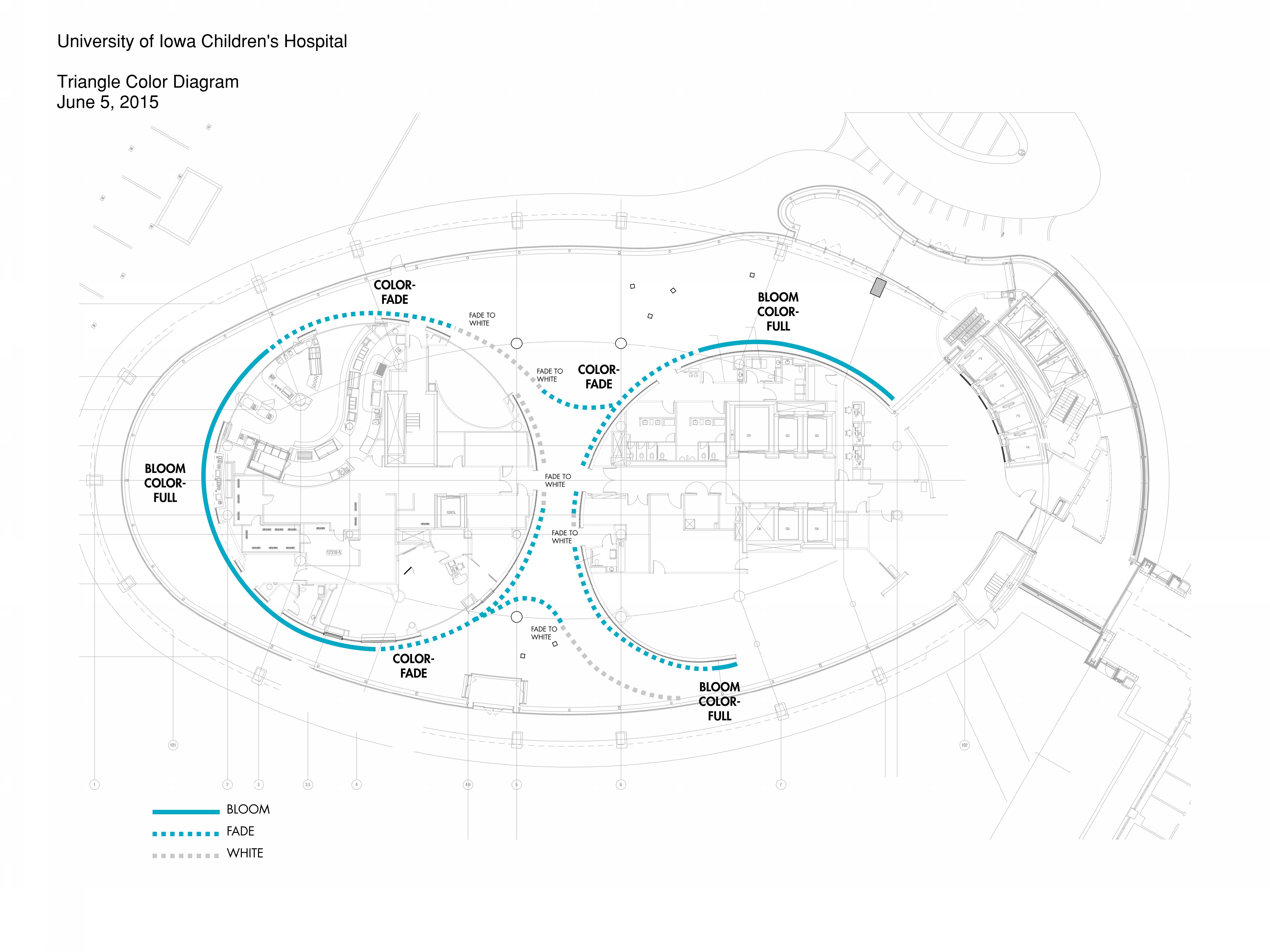
A vibrant, colorful, curved wall art installation, a premier feature of the new $360 million, 14-story University of Iowa Children’s Hospital project, designed by Foster & Partners with Heery International preforming as Architect of Record, stretches the entire length of the main area’s two-story lobby. Called “The Blooming Wall,” the installation consists of 2,800+ extruded aluminum triangles attached to 1,000+ linear feet of radius wall. Windows, doors, and signage interrupt the continuous feature, making layout difficult. With the art installation one of the last scheduled construction items and its challenging nature of curved design, Gilbane Building Company utilized advanced 3D scanning technology as part of a virtual design and construction (VDC) solution to ensure quality control throughout the lifespan of the project.
CHALLENGES
Within days of stepping onsite at the new children’s hospital project in Iowa City, Gilbane’s Sr. Project Executive, Jennifer Halstead, knew they’d need to take special measures to handle the inherent challenges of this high-design curved building project. They understood right away this was no job for a straight tape measure and a plumb bob, but rather it required bringing in a team to do advanced 3D scanning and analysis.
Due to the irregular, radial form of the building, deviations between built conditions and the artist’s design intent were expected. Accurate documentation of such conditions were needed before a solution could be found.
As Alexis Carver, Senior VDC Manager at Gilbane, notes, “The heart of the challenge was that the art installation drove the construction process and design of the wall layout, not the other way around.” The art affected the timing, too, as they planned to finish the lobby last to allow for fabrication of artwork.
All 2,800 extruded aluminum triangular pieces needed to be installed at a very high tolerance—5” on center with +/-1/4” accuracy at the outermost point of the triangle off the wall. Holding this tolerance would be problematic on its own. When combined with layout and construction tolerances for six layers (two layers of plywood first, followed by four layers of sheetrock)—the team faced a very daunting challenge.
To help illustrate the point, check out this video, which highlights the project’s framing and drywall phases of scanning as well as design development, starting with framed openings and basic layout to critical triangle placement to the final layout.
SOLUTION
Gilbane used the FARO Focus3D X 330 Laser Scanner to capture data from “The Blooming Wall” —the two-story curved wall that runs around the lobby base—in order to confirm locations of the metal stud framing and to set the openings prior to sheetrock installation at a location that ensured no triangle would be partially in an opening in the finished product. The Gilbane team scanned throughout the construction lifecycle—from the framing to the sheetrock to continue to verify the face of drywall and confirm it was within construction tolerances. Design tolerances for the art installation were tighter than the standard construction tolerances of the supporting structure, so verification and slight adjustments to the model continued as construction progressed. This ensured all components were installed correctly and that the modeled conditions aligned with the as-built conditions. It also allowed the trade partners an opportunity to provide constructability input and put together a plan to develop their own triangle installation documentation.
Gilbane Building Company, the project’s Construction Manager, worked collaboratively with the trades through each iteration, providing data as they needed it. The team digitally modeled the 2,800+ extruded aluminum triangles, locating them within tolerance at 5” on center along the entire length of the lobby wall laser scan. The scanning and analysis allowed them to identify instances where adjustments to wall openings were—and were not—needed to meet aesthetic tolerance.
The end deliverable Gilbane provided to the architect was a plan to approve the color gradient pattern as well as for the fabricator to incorporate the final layout into their shop drawings. Gilbane produced plans, section cuts, and 3D views of the model to show exactly how many extruded triangles were required for the art feature, and the exact length, color combination, and location for each of the individual triangles. In addition, these drawings also revealed the lobby design’s rainbow-patterned color gradient, showing where each color starts, where it ends and where it transitions to the next color.
With regard to developing the scanning process, Ken Grothman, VDC Engineer with Gilbane, says, “We had to be very thoughtful and take our time, with a methodical scanning approach. We were only moving about 15 feet between each scan location in order to get a really good solid look at the wall framing from every angle.” Additionally, they had to ensure the accuracy of the documents they produced. Grothman adds, “Having the laser bounce all around the studs produces a “fuzzy” quality that diminishes our ability to pinpoint framing locations.” He further notes, “As the wall curved away at the extents of each scan, accuracy and fidelity started to diminish, resulting in the short distances between scans for sufficient—and more importantly accurate—scan overlap.”
Additionally, to manage the complexities of working at a jobsite under construction (i.e. there is a lot of worker and equipment traffic in the building), much of the scanning occurred at the end of shifts to minimize the amount of people, tools and supplies scanned and cluttering up the point cloud. This allowed the scanning team, which consisted of two people running two Focus3D X 330 Laser Scanners for most of the project, to see as much of the wall as possible. Then, in processing, the scanning team ensured they applied appropriate filter settings in the software to remove extra data, including people and tools.
Grothman notes that the bulk of processing utilized SCENE Software with Autodesk® Recap™ acting as a file converter to get the point cloud into an Autodesk-friendly format. The majority of the processing focused on filtering stray data points and manually cropping scans—because the extents of each scan were affected by the wall curving away—and removing scan debris (i.e. people, moving equipment, glass reflections, etc.). He says, “Once we had the scans pulled down to only the best data, registration (assembling all the scans into one cloud) was next. We used target-based registration to begin and with a fine tooth comb ensured the tightest registration tolerances by removing poor sphere fits and visually inspecting the cloud to verify accuracy.”
Cloud to cloud registration followed with custom parameters (i.e. very close search distances and high sampling values) to bring the scans the rest of the way home. The end result was a point cloud with an average tolerance of just over 1mm, an extremely favorable result for this feature’s tight tolerances.
Three Sets of Scans
Gilbane’s scanning team currently completed three rounds of scanning during the different phases of the project: first with just the metal stud framing installed, then after installing the intermediate layers of plywood, and finally at the end of the drywall installation. Scanning at the different phases of construction allowed the team to head off any issue in real-time. For example, they could test for any bulging or misalignment before too much drywall went up.
Framing phase
The wall is curved along multiple radii. As framing was installed, the team verified that the studs followed the architectural design. For this first set of scans at the framing stage, the crew performed more than 100 scans to maintain very short distances between each scan location.
Initial drywall phase
After the first two layers of drywall were installed, Gilbane completed the same set of scans to ensure the drywall still followed the curve. Was an unintentional change to the curvature accidently introduced during installation? For this stage, with the less reflective drywall surfaces, the team only scanned 60 times to compile an accurate point cloud.
Final layer of drywall
Scanning at the final layer verified that the in-place product would support the modeled layout of the triangles.
In total, approximately 250 scans completed the point cloud over the course of the three- to four-month period.
RESULTS
Prior to laser scanning, the initial construction schedule showed 80 working days for artwork installation. Once Gilbane stepped in with the FARO 3D laser scanning and modeling solutions, the team reduced the planned installation by 40 days (approximately two months) for this critical sequence item due to a more efficient and accurate layout. Through use of the laser scanner, the team generated a constructible solution and installation-ready documents to assist the trade contractors involved with final installation. In addition, the entire team, including the fabricator, gained a thorough understanding of the layout process, specifically, the critical layout points to ensure that the triangle spacing did not accumulate tolerances through layout around the building.
Gilbane’s team completed the process of the scans end-to-end, from scanning on-site, to processing, and importing the scan in Autodesk® Revit®. Gilbane also did the final analysis, finding the issue areas and documenting the problems as they came up, rather than having the trade contractors incorrectly working on a section and needing to go back to make adjustments.
The scanning process and model overlay provided the entire team with a very high confidence in this feature art installation’s plan at a critical point in the project.
CONCLUSION
Ultimately, the laser scans facilitated a highly detailed fabrication and installation plan, and the subsequent QA and QC measures for this high-design, curved and complex art installation. Gilbane’s comprehensive 3D laser scanning solution, consisting of FARO Focus3D Laser Scanners, SCENE Software and a suite of Autodesk® Software, was instrumental in implementing a time sensitive and collaborative approach. In doing so, Gilbane was able to benefit by:
- Maximizing schedule optimization
- Reducing project costs
- Increasing team communication, collaboration and cohesion
- Ensuring higher project quality
- Creating a safer jobsite through better understanding of project workflow
Related Stories
| Jul 10, 2013
World's best new skyscrapers [slideshow]
The Bow in Calgary and CCTV Headquarters in Beijing are among the world's best new high-rise projects, according to the Council on Tall Buildings and Urban Habitat.
High-rise Construction | Jul 9, 2013
5 innovations in high-rise building design
KONE's carbon-fiber hoisting technology and the Broad Group's prefab construction process are among the breakthroughs named 2013 Innovation Award winners by the Council on Tall Buildings and Urban Habitat.
Sponsored | | Jun 30, 2013
Get your 'Early Bird' entry in for BD+C 30th Annual Reconstruction Awards
The deadline is for BD+C's 30th Annual Reconstruction Awards is July 19, but if you get me a draft of your entry by July 12 (earlier if possible, please!), we'll read it and give you feedback and suggestions that could help you win. We'll give you enough time to rework your entry in time to meet the deadline. We do this "Early Bird" service to help you put together the best possible entry - one that will answer any questions our distinguished jury members may come up with. However, we must emphasize that the BD+C Reconstruction Awards program is a juried competition, so there are no guarantees you'll win. We're just trying to improve your odds. Building Design+Construction is the only publication in its field to recognize the importance of reconstruction in all its forms - historic preservation, adaptive reuse, renovation, fitouts, and reconstruction with addition. And we've been doing it for 30 years. Incidentally, reconstruction accounts for 30-35% of all revenue for AEC firms, so it's a key component of the US/Canada design and construction industry. Send your draft entry to: rcassidy@sgcmail.com. And good luck!
| Jun 28, 2013
Calculating the ROI of building enclosure commissioning
A researcher at Lawrence Berkeley National Laboratory calls building enclosure commissioning “the single-most cost-effective strategy for reducing energy, costs, and greenhouse gas emissions in buildings today.”
| Jun 28, 2013
A brief history of windows in America
Historic window experts from Hoffmann Architects look back at the origin of windows in the U.S.
| Jun 28, 2013
Building owners cite BIM/VDC as 'most exciting trend' in facilities management, says Mortenson report
A recent survey of more than 60 building owners and facility management professionals by Mortenson Construction shows that BIM/VDC is top of mind among owner professionals.
| Jun 27, 2013
Thermal, solar control designs can impact cooling loads by 200%, heating loads by 30%
Underestimating thermal bridging can greatly undermine a building’s performance contributing to heating load variances of up to 30% and cooling load variances of up to 200%, says the MMM Group.
| Jun 20, 2013
Virtual meetings enhance design of University at Buffalo Medical School
HOK designers in New York, St. Louis and Atlanta are using virtual meetings with their University at Buffalo (UB) client team to improve the design process for UB’s new School of Medicine and Biomedical Sciences on the Buffalo Niagara Medical Campus.
| Jun 14, 2013
Purdue, industry partners test light steel framing for seismic safety
A partnership of leading earthquake engineering researchers from top U.S. and Canadian universities and design professionals from the steel industry have begun the final phase of a three-year project to increase the seismic safety of buildings that use lightweight cold-formed steel for their primary beams and columns.
| Jun 11, 2013
Finnish elevator technology could facilitate supertall building design
KONE Corporation has announced a new elevator technology that could make it possible for supertall buildings to reach new heights by eliminating several problems of existing elevator technology. The firm's new UltraRope hoisting system uses a rope with a carbon-fiber core and high-friction coating, rather than conventional steel rope.


