Post-processing computational fluid dynamics (CFD) data is a vital step in order to accurately derive the right conclusions from the models, present the results to decision-makers, and ensure the best product design. Output files generated by CFD simulations are often huge, making it a daunting task to efficiently create effective visualizations.
Design decisions require optimization studies which mean a large number of individual CFD simulations. Years of experience using many popular CFD visualization tools in a wide range of industries has made me realize certain best practices that should always be applied.
In this article, six tips are covered to make post-processing more productive and produce impressive presentations. The illustrations and examples are based on ParaView, a powerful visualization tool, but the tips can be applied to most other tools, as well.
1. Use “state” files to automatically generate pipeline. “State” files are light-weight in size and therefore can be saved at regular intervals without worrying about storage capacity. Never re-generate all the post-processing steps (contours, streamlines, vectors, slices, filters, etc.) again and again for cases with identical/similar geometry. Save and reuse the state file and load it anytime to perform post-processing pipeline on a similar CFD model. This is also extremely powerful for design explorations where differences in modeling scenarios are small or none.
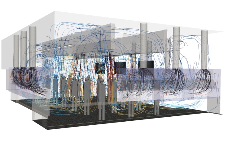
2. Group surfaces, extract zones. This is a big time-saver when your model has a large number of surfaces/zones. Grouping similar geometric entities efficiently changes colors, transparency, displays/hides scenarios, light effects, and visuals. Moreover, zones that the analysis is focused on can be extracted, ultimately making your file easier to handle. The post-processing model below shows where the similar parts have been extracted and grouped.
3. Don’t misuse streamlines. Flow streamlines, pathlines, or stream tracers are a great way to visualize and understand the flow patterns. They are also the most misused visualization method. Too many streamlines, improper seed points distribution, and coloring by a random variable can be the cause of some of the problems.
4. Save what you NEED. This tip is very important when CFD simulations are generating huge amounts of data. In most situations, we know the quantities that are needed for the analysis. By default, CFD tools save many primary and derived scalars/vectors in output files. This implies that the CFD simulations are saving data, for each point of the computational mesh, for a large number of quantities. Think about it, how many times have you used flow variables other than temperature, velocity, and pressure in your reports?
5. Camera, views, lights. Believe it or not, many users try to manually adjust the 3D camera view to get images with the exact same view for different CFD cases. The resulting comparison images from such effort look ugly, to say the least. In ParaView, save/load views, undo them, and even sync camera for multiple cases. Also, use lights in a way that enhances your CFD and makes it easier for your report’s audience.
6. Start with gray scale, and transparency. CFD engineers often create images with a myriad of colors. Having access to the whole color spectrum does not mean we should use them all. Using too many colors does not add any value and instead distracts the viewer from focusing on the message. This is not only true for CFD visualizations but any other visuals and even UI design.
Although these are just a few tips of many for post-processing, Southland’s CFD department does its best to ensure our reports show exactly what the client needs. This means, following these rules to ensure the report can be read efficiently and show the true benefit of the analysis.
About the Author
As a CFD Analyst at Southland Engineering, Abdullah Karimi optimizes designs through CFD modeling for projects and collaborates with engineers to ensure each design meets specific environment standards. His breadth of knowledge regarding data collections, pre-processing data, running CFD simulations, and providing design recommendations have led to successful outcomes on several confidential data center and casino projects, as well as the Mercedes-Benz Stadium in Atlanta.
More from Author
Southland Industries | Feb 6, 2023
Modular electric rooms are the new normal
Southland Industries breaks down the prefabrication benefits of Modular Electric Rooms (MERs).
Southland Industries | Aug 9, 2022
5 Lean principles of design-build
Simply put, lean is the practice of creating more value with fewer resources.


