Retrofits present a multitude of problems. One of the largest pain points is establishing an as-built condition. Older buildings are a hodgepodge of minor and sometimes major undocumented "improvements" that can alter the accuracy of the so called "as-built drawings."
Even accurate drawings become inaccurate as the structure settles and materials begin to drift from the orthogonal perfection assumed in the drawings. It is fair to say that most as-built drawings do not represent the as-built conditions.
Although we rely upon as-built drawings to help us understand the site for our design, their support is as thin as the paper they are printed on. We often price materials, design mechanical systems, and get hardware manufactured only to find, once someone is on site installing the thing, that there was a discrepancy between the as-built drawings and the as-built reality.
For this reason alone, retrofits often carry a higher risk and construction cost. The risk can sometimes be so great that we build new buildings because we don’t want to deal with the uncertainty of an old building.
There has to be a better way to absorb, analyze, and document the existing built world than to rely on documents that probably didn’t match the initial construction.
ScanLAB Showreel from ScanLAB on Vimeo.
Over the past decade, there has been a proliferation of technologies for creating accurate three-dimensional models from the real world. Arguably, the most accurate is Terrestrial LIDAR or laser scanning. Essentially, you attach the laser scanner to a survey tripod and place it inside the building you want to model. The scanner then uses LIDAR to measure the location of points in the space. The end results is a point cloud.
Most people have seen at least one example of a point cloud (they are making their way into pop culture). They often look like a monochrome, jumbled mess of points that have no relationship to each other. From far away, this is absolutely true. Zooming in and paring down the ‘noise’ we can really start to see a point cloud for what it really is: coherent outlines of real-world geometry.
The cost and speed of laser scanning is rapidly falling. Hardware that cost hundreds of thousands of dollars a few years ago now costs tens of thousands. At the same time, software costs have come down substantially and, thanks to a few pioneering software developers, the learning curve is coming down as well. The consumer market is also latching onto technologies like photogrammetry (via Autodesk’s 123D Catch, Microsoft’s PhotoSynth) and depth field mapping (via Google’s Project Tango and Microsoft’s Kinect) making the idea of capturing 3D maps of real world feel less and less like science fiction.
Utilizing point clouds to assess existing conditions as part of a renovation project has immense benefits. Countless ‘issues’ can be identified and resolved before they become problems in the field. Provided we know the right question, the point cloud is able to answer a multitude of inquiries regarding the conditions of the building at the time of the scan.
Let’s take a look at one question in particular: How level is an existing slab?
Using traditional as-built drawings, it would be impossible to know the variation in a slab. This can be a costly adder to a project and one aspect of a project that may not even be discovered during design. This cost is not just a labor and material cost, but can add substantial, unplanned time to tight construction schedules. For example, an unknown floor condition could require additional materials and time to level new floor finishes, or the reconsideration of door sizes and threshold conditions—which could potentially affect items that have already been purchased.
Recently, the CASE team needed to understand the variations in an existing structural slab. The uneven condition of the surface has been recorded in the field notes and our client had concerns. The as-built drawings weren’t any help, but thankfully, we had already created a point cloud. All we needed to do was analyze this data to find the surface variation.
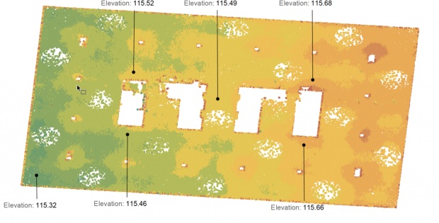
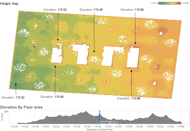 Plan view of the floor slab created from a point cloud. Green areas are the points of lowest elevation, red are the highest. Using this visualization, a designer can quickly understand how the slab varies from west to east. In this case, the variation is almost a third of a foot. Image: CASE
In this fairly simplistic example, we have isolated and extracted the points for two floor slabs. By running a scatter map analysis of the variation across this data set, we were able to visualize and pinpoint areas of greatest transition. This allowed us to highlight high and low points using a color range that allowed all stakeholders to quickly grasp the impact of these slab variations. In this case, the slabs varies to such a degree that amendments and highly-coordinated details were required for the construction team.
The immediate benefit of this process is making an informed decision. Such an analysis can help a team assemble options that can be evaluated against the data to determine the most cost effective, valuable solution for the construction team and, by extension, the owner. In this manner, it gives us another tool to improve the accuracy of our design and coordination process.
Granted, this is a single example of a much larger solution for capturing and analyzing existing conditions, but it illustrates the potential of leveraging point clouds in an AECO project. When thinking about the most effective way to communicate potential construction constraints, or documenting what’s out there, laser scanning can be essential to gain consensus across the entire project team.
Join us in our next segment, where we will investigate the process CASE used to develop a streamlined approach to this analysis. We hope that this article has inspired you to consider Reality Capture on your next improvement project.
Learn more
• If you want to get started with reality capture, all you need is phone and Autodesk's 123D Catch app.
• Jason explains how to process point clouds with Dynamo.
• If you want reality capture on your project, CASE has a reality capture service.
About the Authors: As a Lead Building Information Specialist at CASE, Matthew Nelson is responsible for developing BIM based implementation strategies that focus on scalability and widespread firm adoption. Frustrated by the siloed project delivery process that exists within the AECO industry, Nelson enables teams with an integrated project delivery approach to enhance clarity between project teams by leveraging technology and identifying key struggles between digital and interpersonal communications. He is a board member of the Portland Revit User Group, and is one of the developers of StockRoom, a package for Dynamo that provides access to Revit API. Email: m.nelson@case-inc.com.
As a Senior Building Information Specialist at CASE, Carrie Schulz provides BIM implementation and project support where she focuses on defining clear process management strategies for AECO clients. She is particularly interested in improving the efficiency and efficacy of design processes using a range of technologies in addition to finding creative solutions in a collaborative environment such as CASE. Schulz earned a Master of Architecture from Parsons The New School of Design, and subsequently oversaw several large-scale healthcare and restaurant projects as a designer and BIM manager. Email: c.schulz@case-inc.com.
More from Author
CASE blog | Jul 6, 2015
BIM/VDC training is more than learning the features
Training can be a taxing experience for both the class and the instructor. CASE's Nathan Miller offers four ways to make training more relevant to practitioners.
CASE blog | May 21, 2015
How AEC firms should approach BIM training
CASE Founding Partner Steve Sanderson talks about the current state of software training in the AEC industry and common pitfalls in AEC training.
CASE blog | May 10, 2015
How beacons will change architecture
Indoor positioning is right around the corner. Here is why it matters.

