One of the most important process changes when using 3D building information modeling is that architects and engineers can share more detailed design information with their general contractors prior to beginning site work. Yet, very little has been done to change how that information is communicated to the field. Many construction companies equip project managers in the field with laptops and keep 3D models on a central computer in a construction trailer, but rarely can anyone access and update that shared BIM file during construction planning or to point out problems during actual construction.
Many construction companies simply create their own BIM models from scratch because it’s easier to re-create a model for constructability than it is to adapt a design model to field conditions. In recent months, however, Trimble, a Sunnyvale, Calif., manufacturer of software and hardware for general, steel, concrete, and MEP contractors, released Trimble Field Link, which enables Building Teams to transfer design information from the office to the field using a Trimble RTS Series Robotic Total Station and the Trimble Tablet Rugged PC, a tablet computer with a seven-inch touchscreen that runs the Windows 7 OS.
There are two different versions of the Field Link software, one for MEP contractors and one for steel, concrete, and general contractors. The company has produced field products before, but this is the first with a full 3D model viewer that allows personnel to view 3D DWG and DXF design models in the field.
According to Jim McCartney, Trimble’s Structures segment manager, contractors wanted the ability to use that information, going to and from the field, without having to completely overhaul their processes. With the new systems, he said, “You can take 3D DWG design files and open them in Trimble Field Link to see that file.”
Their earlier generation construction layout solutions, Trimble LM80 and Trimble MEP, were based on the Windows Mobile OS, running on the Trimble Nomad handheld computer. Capable layout solutions in their own right, these existing solutions allow contractors to take blueprint or CAD data to the field and back to the design model. But with the explosion of 3D BIM, general contractors wanted capabilities that were simply impossible on that platform. The company’s customers asked for a way to detail reports and information about what is going on in the field so this information could be easily communicated back to BIM and CAD managers.
To do this, a field-reporting feature was added to allow contractors to report a trouble area, take photographs, and document actual position in the field to send back to the office.
“One of the things we’ve seen from general contractors is they’re using these devices for quality control. The tablet not only allows you to measure points, widths, and tolerances, it also allows you to go back in and check the specifications in the field,” McCartney said.
The system allows you to document deviations from those specs by attaching photographs to reports. You can also see where a deviation is located within your site by setting x, y, z coordinates within your report. The field-reporting feature exists in both the MEP and Structures versions of the software. Using the tablet’s built-in digital camera, field personnel can document a construction problem and save site photos, then communicate that information back to project managers by typing in text to describe the scene in the photograph. The field-reporting feature then creates a PDF file with a name, date, time, contractor name, job name, and coordinate values of the position of the construction issue that can be e-mailed to other Building Team members. This coordination capability may save a project from disaster.
For example, it is not unusual for misaligned anchor bolt positions to go unreported because field personnel sometimes choose not to fill out reports unless the anchors are significantly misaligned. By allowing even small problems to be reported from the field with a few clicks, more errors can be reported—and resolved.
“We had a customer tell us that in one instance he made the decision to ignore a misaligned anchor bolt due to the time it would take to generate a report,” said McCartney. “It cost him $35,000 to fix. He said if he could have generated a report and got a response immediately, he would have reported it.”
Trimble Field Link software automatically shows positional data of a project via defined points in an area. At any time you can click the Trimble “orb” from within Trimble Field Link to display a menu ribbon. You can open a simple directory path (just like a PC directory tree) with all of your job files from the ribbon. Each job is expandable to show the points, lines, arcs, and other positional data in the job, when they were created, and when they were last modified. From the Create Data screen on the ribbon you can create new end points and positions and also attach design attributes to points.
Additonally, you can select data from a mapview or a pointview, select a specific point, and zoom right in to that point. Those points and measurements can be used to calculate things like the magnitude of concrete pours and how much steel or concrete will be required for embeds. MEP coordination is one of the areas of a project that benefits most from using BIM, and the Trimble Field Link for MEP solution automates several common job site tasks, such as defining hanger points and sleeve locations.
The Trimble Field Link model viewer uses layers to highlight or hide different views of piping, ductwork, and wiring depending on what you want to look at. Once a model has been opened within the Trimble Field Link software, you can use the “orbit” function to look at a 3D view and pan and zoom to show its complexity. This field representation lets you see the 3D model as either a solid view or wireframe.
You can also turn layers on and off, isolate footings, and show other views just like in a native model. The MEP version can also be used to measure jobsite productivity.
“MEP contractors are better able to understand productivity rates on common procedures like laying out attachment points on pan decking,” said Rob Miller, Trimble MEP segment manager. “Once they’ve done several jobs with the solution, they can then plan layout productivity estimates for future bids. That can increase their bottom line on future projects.”
The key to the new product is its simplicity. “We did not want to overcomplicate the process by bringing in a model viewer that wasn’t simple enough to work with in the field,” McCartney said. “The viewing objective was to enhance capabilities but to never forget the simplicity factor.” BD+C
Related Stories
| Jun 1, 2012
K-State Olathe Innovation Campus receives LEED Silver
Aspects of the design included a curtain wall and punched openings allowing natural light deep into the building, regional materials were used, which minimized the need for heavy hauling, and much of the final material included pre and post-consumer recycled content.
| Jun 1, 2012
New York City Department of Buildings approves 3D BIM site safety plans
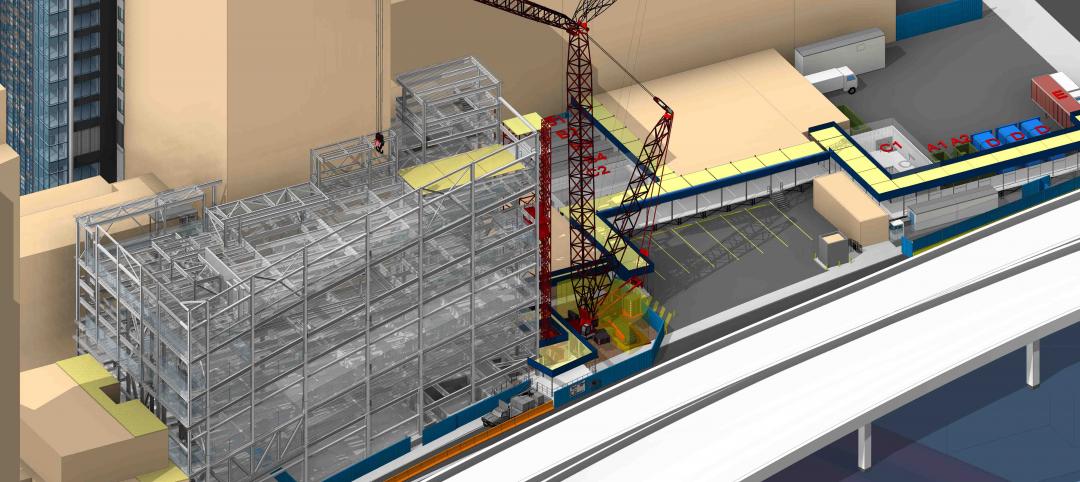
3D BIM site safety plans enable building inspectors to take virtual tours of construction projects and review them in real-time on site.
| May 31, 2012
3 Metal Roofing Case Studies Illustrate Benefits
Metal roofing systems offer values such as longevity, favorable life cycle costs, and heightened aesthetic appeal.
| May 31, 2012
5 military construction trends
Defense spending may be down somewhat, but there’s still plenty of project dollars out there if you know where to look.
| May 31, 2012
New School’s University Center in NYC topped out
16-story will provide new focal point for campus.
| May 30, 2012
Construction milestone reached for $1B expansion of San Diego International Airport
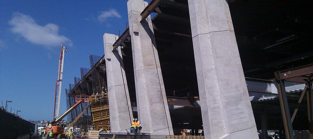
Components of the $9-million structural concrete construction phase included a 700-foot-long, below-grade baggage-handling tunnel; metal decks covered in poured-in-place concrete; slab-on-grade for the new terminal; and 10 exterior architectural columns––each 56-feet tall and erected at a 14-degree angle.
| May 29, 2012
Torrance Memorial Medical Center’s pediatric burn patients create their version of new Patient Tower using Legos
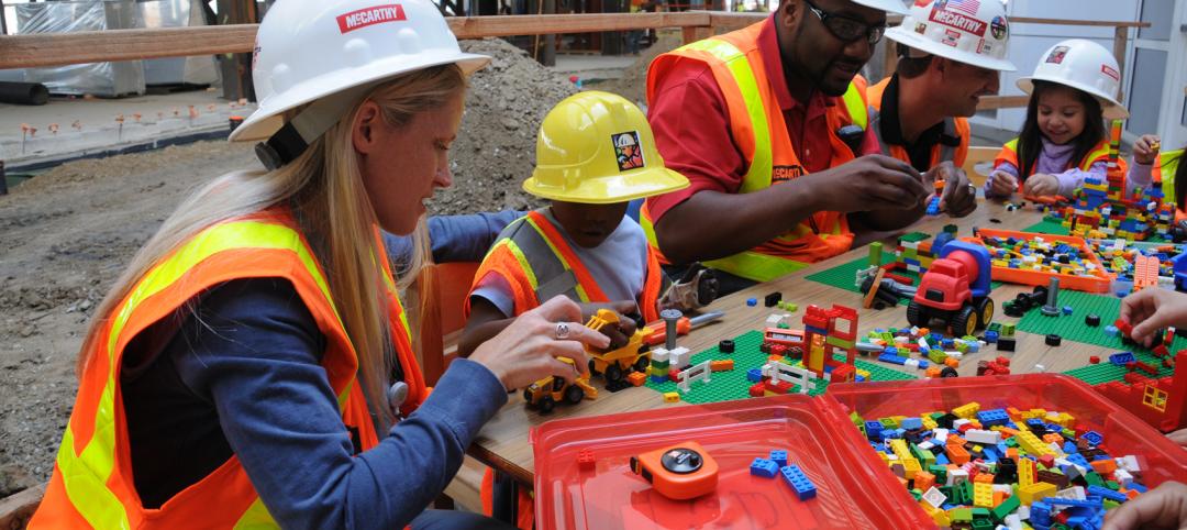
McCarthy workers joined the patients, donning construction gear and hard hats, to help with their building efforts.
| May 29, 2012
Reconstruction Awards Entry Information
Download a PDF of the Entry Information at the bottom of this page.
| May 24, 2012
2012 Reconstruction Awards Entry Form
Download a PDF of the Entry Form at the bottom of this page.
| May 23, 2012
Arizona Army National Guard Readiness Center awarded LEED Silver
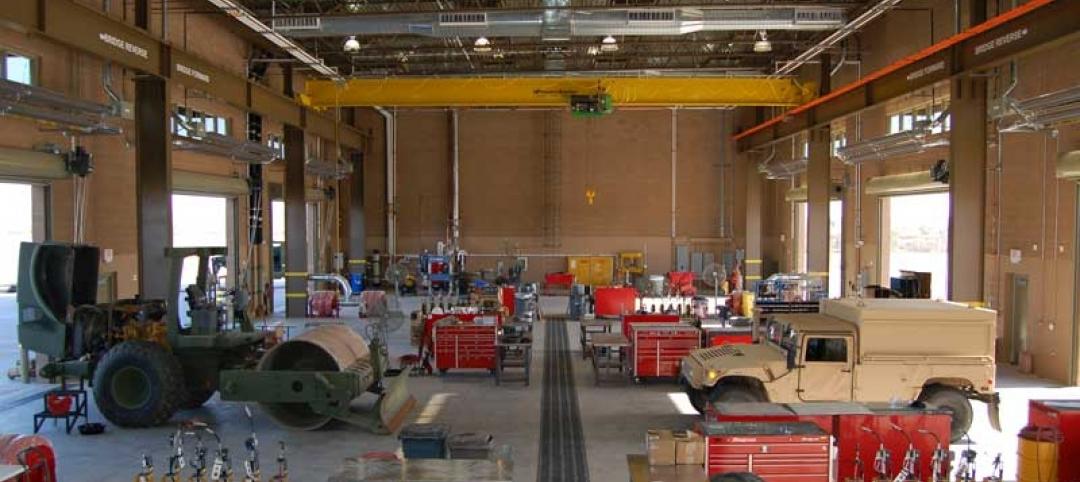
LEED certification of the AZ ARNG Readiness Center was based on a number of green design and construction features SAIC implemented that positively impacted the project and the broader community.


