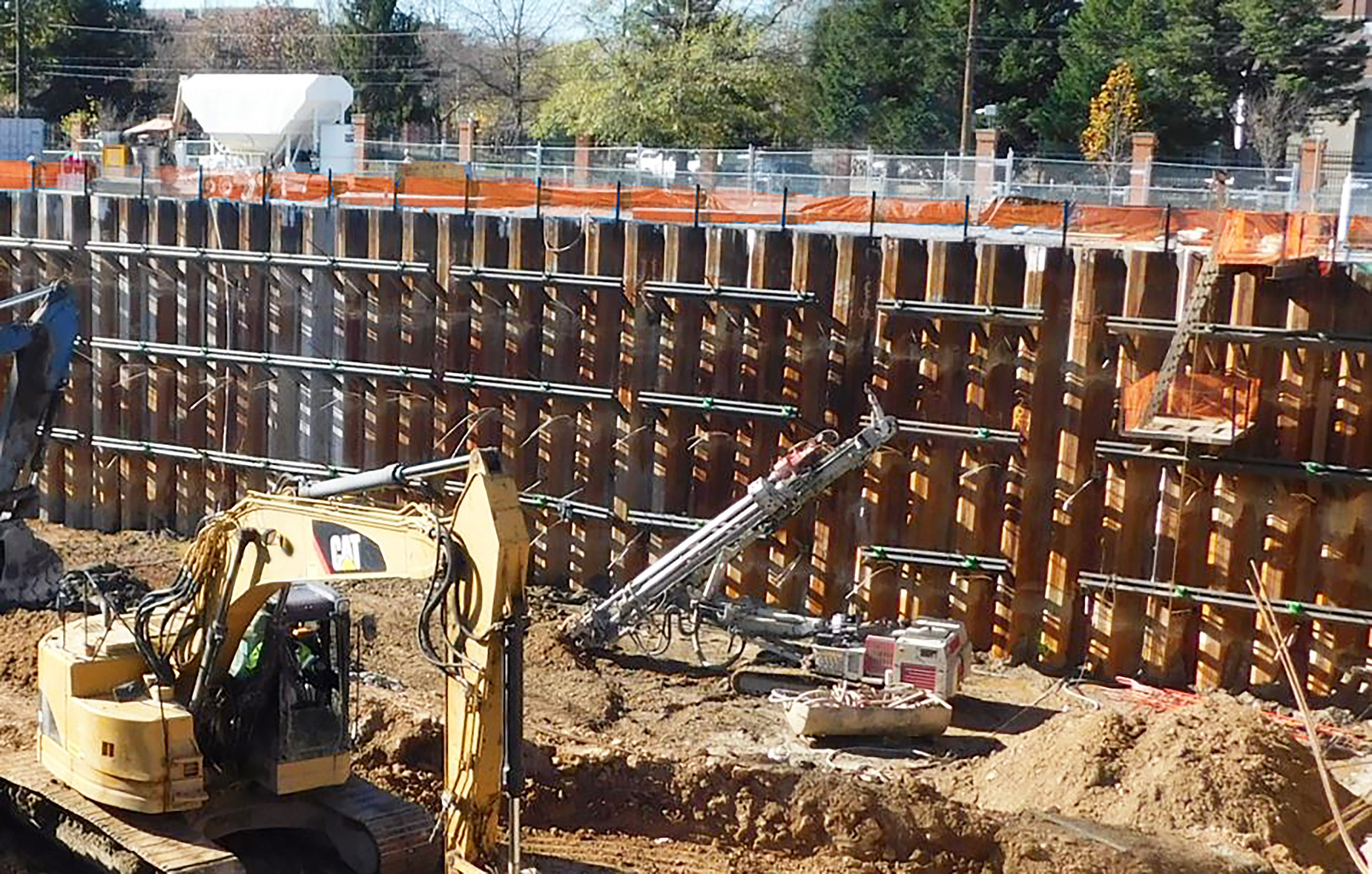
Steel sheet piles have more than a century-long history of being used to support excavations for buried structures (Figure 1). During the construction process, the sheet piles traditionally provide earth retention and, in conjunction with a dewatering system, control of subsurface water into the construction site (both for leakage through the sheet pile system and for seepage below the sheet pile system).
In contemporary building development projects and in the context of subsurface water control, the role of the sheet pile system is typically temporary, until a dedicated waterproofing layer is applied to the building’s foundation wall.
However, for projects that do not include moisture-sensitive below-grade spaces, project teams sometimes elect to forego foundation wall waterproofing and rely instead on sheet piles alone for semi-permanent or permanent reduction of subsurface water. One example project application is a wall demarcating adjacent portions of a multi-phased below-grade garage (where subsequent phases of the below-grade structure will be constructed several years after the initial phase).
To implement this sheet pile “water management wall” approach successfully, multidisciplinary teams must closely coordinate to set appropriate expectations, assign and execute design and construction roles, and incorporate technical considerations that are not otherwise a focus of traditional sheet pile support of excavation (SOE) design. In this article, we explore aspects of sheet pile subsurface water control systems for buildings organized by the project’s primary stakeholders and considerations within their purview.
Owner/Developer
It is vital that the Owner/Developer’s project team be informed with reasonable expectations of what will be required from their capital program during the service life of a building’s below-grade water management system. Fundamentally, this includes the knowledge that the success of the sheet pile water management wall’s long-term performance will rely on maintenance activities. In developing a program to manage periodic water infiltration (leakage) in service, the Owner/Developer should understand that such a program will likely include the following:
- Accessing and cleaning an internal drainage system at the base of the sheet pile wall.
- Maintaining the drainage discharge system (e.g., sump pumps, piping, and associated backup emergency power).
- Accessing the interior face of the sheet pile wall to perform leak remediation measures (e.g., chemical grout injection) if the leakage increases to a level the drainage system cannot reasonably manage.
- Treating contaminated groundwater (if applicable; see Environmental Engineer section below).
Architect
As part of their role in developing the project’s overall design documentation, the Architect prepares construction drawings and specifications and coordinates with subconsultants who prepare specific aspects of the design. The sheet pile water management wall is inherently multidisciplinary, but the architectural details can help synthesize the basis-of-design for the architectural, structural, and plumbing features of the design.
If other foundation elevations or the underside of the slab is covered in waterproofing, the Architect (and their design consulting team, e.g., a Building Enclosure consultant) should consider and establish details for the integration between the sheet pile water management wall and the below-grade waterproofing system.
If the Architect decides to incorporate an interior partition to conceal the sheet pile wall, the design should account for the Owner’s building management personnel's continuing need to periodically access the interior face of the sheet piles to perform the maintenance activities described previously. If interior programming would not allow the partition to be offset from the wall by a substantial distance, the design should seek to avoid scenarios where a partition that is closely offset from the sheet piles unnecessarily commits the Owner to costly and logistically challenging Confined Space operations or total partition demolition upon the need to access the sheet pile wall face.
One appropriate design strategy would be to use partition systems that can be readily removed/reinstalled by the Owner’s maintenance personnel. Other design decisions that can be reflected on the architectural details include raising the bottom of the partition on a concrete curb to create a “gutter” to collect and divert leakage water to internal drains at the bottom of the sheet pile wall. The collected leakage water would be directed to sump basins that pump the water from the below-grade spaces.
Structural Engineer
The Structural Engineer of Record (SEOR), in addition to their role related to the below-grade building design, conventionally develops the structural basis-of-design for the SOE system, using site-specific conditions and parameters provided by the Geotechnical Engineer. Sheet pile design is often specified as a Delegated Design scope of work, i.e., with the final design completed by an engineer retained by the construction team. From the standpoint of designing for the sheet pile wall’s water leakage control function, the SEOR should consider:
- Limiting the number of penetrations through the sheet pile wall to those that are structurally essential (e.g., at tie-back systems) to attempt to control the amount of water leakage and detailing those penetrations to limit water leakage. After the construction of interior floor slabs and once they have the capacity to brace the sheet pile wall, the structural engineer can consider recommending removal of now-redundant tie-back systems, enabling the abandoned openings to be closed in a watertight manner (e.g., welded cover).
- Requiring that the final design of the sheet pile bracing elements (e.g., walers) be positioned to avoid creating continuous interruptions to the vertical flow path along the face of the sheet piles (Figure 2). Because an obstructed flow path is more likely to cause leakage to be diverted to an unintended location (e.g., wetting and deteriorating the partition sheathing or entering the below-grade building space); it should flow relatively uninhibited to the leakage collection system at the base of the wall. Similarly, the SEOR can design the below-grade building structure to avoid interacting with the sheet pile wall in a manner that frequently interrupts the leakage flow path.
- Designing the below-grade building structure at intermediate slab edges to avoid restricting future access to the sheet pile face for leak remediation.
- Where the sheet pile system is located below the groundwater table elevation, requiring that the final design of the system resists hydrostatic pressure, including where the sheet piles interface with the below-grade building structure.
Geotechnical and Environmental Engineers
The Geotechnical Engineer evaluates the existing subsurface and groundwater conditions at the site. Using this information (e.g., groundwater table elevations and anticipated fluctuations, soil type and stratigraphy, soil permeability, etc.), they can identify feasible SOE system types for consideration by the project team. If sheet piles are to be used as a semi-permanent or permanent water management wall, the Geotechnical Engineer can select reasonable leakage criteria for the sheet piles, which is an important parameter associated with the water management wall strategy.
Leakage criteria can be informed by available industry references. For example, the Naval Facilities Engineering Systems Command (NAVFAC) publishes the Soil Mechanics Design Manual 7.01 which contains information related to seepage criteria, including the following excerpt: “In pervious sand and gravel… the quantity of water passing through intact interlocks may be as much as 0.1 gpm per foot of wall length for each 10 ft differential in head across sheeting, unless special measures are taken to seal interlocks.” The determination of leakage criteria should also be inclusive of specific attributes of the basis-of-design of the sheet pile wall (e.g., penetrations from soil tie-back anchors).
Moreover, the Geotechnical Engineer should identify the risks, if applicable for the project region and soil and groundwater conditions, of mineral formation (e.g., iron ochre) on the sheet pile design strategy. The Geotechnical Engineer typically also evaluates the need for the sheet piles to serve a cutoff function to control seepage.
Some below grade structures in regions such as Washington, DC, have experienced failures of sub-grade drainage systems as a result of iron ochre. Iron ochre can decrease the ability of a drainage system (such as a sheet pile leakage collection system) to function by clogging drain openings and pipes (Figure 3). Such clogging can be detrimental to the Owner’s maintenance program associated with the drains. Accordingly, in areas with known issues with iron ochre or drainage performance problems, a study of soil/groundwater chemistry should be performed to inform on the risk of iron ochre and other contaminants.
The Environmental Engineer provides recommendations for treating groundwater for contaminants, if applicable.
General Contractor
As part of planning to implement the construction of the below-grade building structure, the General Contractor often influences the selection of the SOE system based on factors including property line considerations, construction logistics, schedule, cost, sequence of building construction, and input from their SOE Trade Contractor. The General Contractor also typically controls the project’s temporary dewatering program, which must be coordinated with the sequencing of bringing the sheet pile water management wall (and its leakage collection drainage system) into service at the appropriate time.
SOE Trade Contractor and Sheet Pile Manufacturer
Using the project design team, their experience, and information from the Sheet Pile Manufacturer and SOE delegated-design engineer retained by the construction team, the SOE Trade Contractor completes the final design of the selected SOE system and then executes its construction. Prior to project bidding, the SOE Trade Contractor should review and confirm the feasibility of the leakage and seepage basis-of-design established by the design team, including obtaining input from the Sheet Pile Manufacturer. The SOE Trade Contractor and Sheet Pile Manufacturer may consider the following as they plan how they will deliver the sheet pile water management wall to meet the project’s criteria:
- Sheet Pile Construction Methods: Careful control of pile driving to minimize deviations from plumb to maximize contact within the interlocks can help limit leakage.
- Sheet Pile Interlock Details (Figure 4): Continuously welded interlocks between sheet piles after installation provide the most reliable resistance against sheet pile water leakage. If welding interlocks cannot be accommodated by the project budget, leakage-mitigating sealants (e.g., hot-applied bituminous products or cold-applied water-swelling products) can be applied to the sheet pile interlocks prior to pile driving.\
- Shop Drawing Phase: Detailed shop drawings showing sheet pile features (e.g., interlock details, bracing details, transitions to adjacent systems, typical penetration types and how they will be treated to resist water penetration) are critical to this process. The shop drawings should also include repair methods for sheet piles that separate from each other or become misaligned during sheet pile driving.
While the above methods can help the sheet pile water management wall meet the project's leakage criteria, the ability to implement them can be impacted by sequence of the overall project's construction activities (i.e., top-down versus bottom-up construction sequencing, which is not discussed in detail in this article). With that said, the project team should review if/how construction sequencing affects the leakage mitigating strategies selected for the sheet pile wall.
Plumbing Engineer
After the project’s permissible leakage rate is established, the Plumbing Engineer designs the internal drainage systems to collect and divert sheet pile leakage to sump basins during the service life of the building. This includes designing the appropriate drainage system layout, drain types and quantity with consideration to project-specific aspects of the sheet pile wall (e.g., locating drains directly below vulnerabilities such as at end conditions of the sheet pile wall where it meets adjacent below-grade structures).
Closing Remarks
Steel sheet piles can serve as part of a semi-permanent or permanent water management strategy for below-grade spaces where long-term management of leakage is not contrary to the function of the interior space. The successful execution of this strategy is dependent on realistic and well-communicated expectations, an integrated mindset and coordinated effort between a variety of project design, construction, and ownership entities.
Related Stories
Energy Efficiency | Aug 9, 2024
Artificial intelligence could help reduce energy consumption by as much as 40% by 2050
Artificial intelligence could help U.S. buildings to significantly reduce energy consumption and carbon emissions, according to a paper by researchers at the Lawrence Berkeley National Laboratory.
Sponsored | Healthcare Facilities | Aug 8, 2024
U.S. healthcare building sector trends and innovations for 2024-2025
As new medicines, treatment regimens, and clinical protocols radically alter the medical world, facilities and building environments in which they take form are similarly evolving rapidly. Innovations and trends related to products, materials, assemblies, and building systems for the U.S. healthcare building sector have opened new avenues for better care delivery. Discussions with leading healthcare architecture, engineering, and construction (AEC) firms and owners-operators offer insights into some of the most promising directions. This course is worth 1.0 AIA/HSW learning unit.
Data Centers | Aug 8, 2024
Global edge data center market to cross $300 billion by 2026, says JLL
Technological megatrends, including IoT and generative AI, will require computing power to be closer to data generation and consumption, fueling growth of edge IT infrastructure, according to a new JLL report.
K-12 Schools | Aug 8, 2024
New K-12 STEM center hosts robotics learning, competitions in Houston suburb
A new K-12 STEM Center in a Houston suburb is the venue for robotics learning and competitions along with education about other STEM subjects. An unused storage building was transformed into a lively space for students to immerse themselves in STEM subjects. Located in Texas City, the ISD Marathon STEM and Robotics Center is the first of its kind in the district.
Green | Aug 7, 2024
Major cities worldwide set building performance standards
Cities around the world are setting building performance standards (BPS) as a key measure to cut emissions and meet climate targets, according to a report from JLL.
Education Facilities | Aug 4, 2024
A former supersonic wind tunnel becomes a new educational facility for transportation design
The Mullin Transportation Design Center at ArtCenter College of Design in Pasadena, Calif., provides access for full-scale vehicular models, replicating a professional design studio.
University Buildings | Aug 1, 2024
UC Riverside’s student health center provides an environment on par with major medical centers
The University of California, Riverside's new Student Health and Counseling Center (SHCC) provides a holistic approach to wellness for students throughout the UC Riverside campus. Designed by HGA and delivered through a design-build partnership with Turner Construction Company, SHCC provides healthcare offerings in an environment on par with major medical centers.
MFPRO+ News | Aug 1, 2024
Canada tries massive incentive program to spur new multifamily housing construction
Canada has taken the unprecedented step of offering billions in infrastructure funds to communities in return for eliminating single-family housing zoning.
Government Buildings | Aug 1, 2024
One of the country’s first all-electric fire stations will use no outside energy sources
Charlotte, N.C.’s new Fire Station #30 will be one of the country’s first all-electric fire stations, using no outside energy sources other than diesel fuel for one or two of the fire trucks. Multiple energy sources will power the station, including solar roof panels and geothermal wells. The two-story building features three truck bays, two fire poles, dispatch area, contamination room, and gear storage.
Contractors | Aug 1, 2024
Nonresidential construction spending decreased 0.2% in June
National nonresidential construction spending declined 0.2% in June, according to an Associated Builders and Contractors analysis of data published today by the U.S. Census Bureau. On a seasonally adjusted annualized basis, nonresidential spending totaled $1.21 trillion. Nonresidential construction has expanded 5.3% from a year ago.


