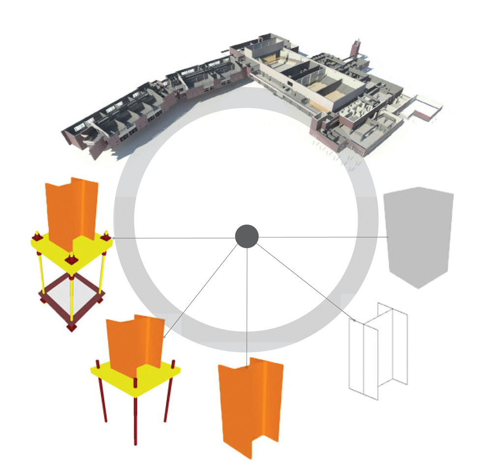
In 2008, the American Institute of Architects released its first BIM contract document—AIA E202 Building Information Modeling Protocol Exhibit—which outlined five “levels of development” (LOD 100-500) for defining the amount of detail in a particular BIM model. E202 provided basic definitions of each LOD but left a lot open to interpretation.
“The E202 was a huge first step in that it provided the first viable vehicle for defining a BIM model at the element level and enabling downstream users to rely on it,” says James Bedrick, FAIA, LEED AP, Founder and Principal of AEC Process Engineering (www.aecpe.com). “Practitioners found, though, that the LOD definitions were being interpreted differently, and that there was a need for more clarity. What does LOD 200 specifically mean, for example, for a door?”
None of the LODs offered a graphical representation of what a model at that level would look like or detailed instructions for how to use models in each LOD for a variety of disciplines. The document, which the AIA has since updated and published as the AIA G202-2013 Project Building Information Modeling Protocol Form (June 2013), had no specific rules or requirements for exactly what’s in a model at each level. As a result, design firms, general contractors, and subcontractors have no idea exactly what they would be handing off or receiving by way of the BIM model.
Level of Development Specification Definitions
• LOD 100 — The model element may be graphically represented in the model with a symbol or other generic representation, but does not satisfy the requirements for LOD 200. Information related to the model element (i.e., cost/sf, tonnage of HVAC, etc.) can be derived from other model elements.• LOD 200 — The model element is graphically represented within the model as a generic system, object, or assembly with approximate quantities, size, shape, location, and orientation. Nongraphic information may also be attached to the model element.
• LOD 300 — The model element is graphically represented within the model as a specific system, object, or assembly in terms of quantity, size, shape, location, and orientation. Non-graphic information may also be attached to the model element.
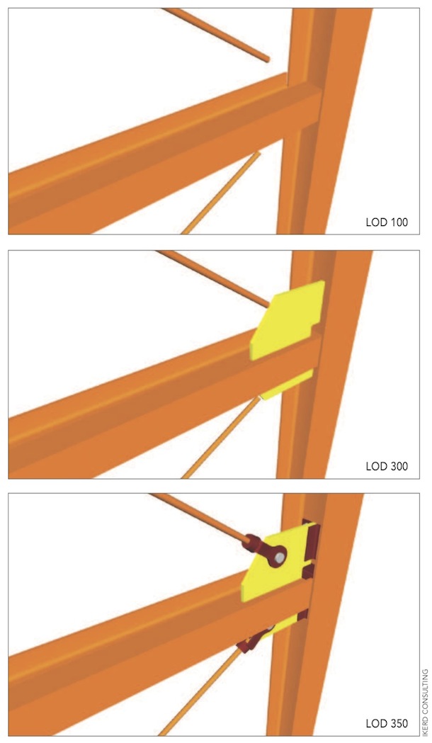
• LOD 350 — The model element is graphically represented within the model as a specific system, object, or assembly in terms of quantity, size, shape, orientation, and interfaces with other building systems. Nongraphic information may also be attached to the model element.
• LOD 400 — The model element is graphically represented within the model as a specific system, object, or assembly in terms of size, shape, location, quantity, and orientation with detailing, fabrication, assembly, and installation information. Nongraphic information may also be attached to the model element.
• LOD 500 — The model element is a field-verified representation in terms of size, shape, location, quantity, and orientation. Nongraphic information may also be attached to the model element.
Source: BIMForum and American Institute of Architects
A new standard promises to lend much-needed clarity to the BIM model detail issue. BIMForum, a multidisciplinary group of BIM users, has released its first BIM deliverable document, the Level of Development Specification. Working under an agreement with the AIA, the BIMForum LOD committee added context and meaning to the AIA G202-2013 definitions for levels 100, 200, 300, and 400, and added a new level (350) for trade coordination. It enables Building Teams to specify and articulate with a high level of clarity the content and reliability of BIM models at various stages, allowing downstream users to clearly understand the usability and limitations of models they are receiving. It’s organized by CSI Uniformat 2010, but expands the subclasses to Level 4 to provide a detailed breakdown and more clarity to the element definitions.
“The key to being able to break out of this quasi-definition cycle is collaboration,” says James Vandezande, AIA, Principal at HOK (www.hok.com), who served on BIMForum’s LOD committee. “It’s a stepping stone to get from document deliverables to model deliverables. This particular stepping stone is the tool that levels expectations between different stakeholders and provides an apples-to-apples comparison.”
“The LOD Specification is not prescribing a particular progression or approach for creating models,” says Jan Reinhardt, Principal at Adept Project Delivery (www.adeptprojectdelivery.com) and Co-chair of the LOD committee. “It only provides clear language for communicating, describing, and agreeing on a progression and quality of a model that is specific for a particular project.”
Built by a Building Team
The LOD committee was set up on a multidisciplinary basis, with Reinhardt (a GC) and Bedrick (an architect) overseeing committee members organized in several domain-specific groups (e.g., structural, interior construction, exterior skin). Each group had one construction professional and one designer to represent their respective points of view during the development process.
LOD 500: The coming O+M BIM model
Early on in the process of deciding what to include in the first Level of Development Specification, the BIMForum LOD committee concluded that level 500 would have to be put on hold. AIA E202 defines LOD 500 this way: “Model elements are modeled as constructed assemblies, actual and accurate in terms of size, shape, location, quantity, and orientation. Non-geometric information may also be attached to modeled elements.”As the industry struggles with the concept of using BIM models for facilities management (FM) tasks, this definition could be construed to be an operations and maintenance level, or as a model for as-built conditions.
“For the first phase of the rollout, we decided to concentrate on levels 100-400 as a starting point,” says Jan Reinhardt, Principal at Adept Project Delivery and Co-chair of the LOD committee. Reinhardt says the committee felt that many common FM-related tasks could be accomplished by using lower-level BIM models, especially when it comes to document management.
A growing number of building owners are demanding BIM models that can be used for FM purposes, but there is little consensus on how to achieve this goal. At a BIMForum meeting last winter in Tacoma, Wash., some of the concerns addressed were: Whose responsibility is it to input all model information into a system to hand off to facilities managers? What system is to be used if not specified by the owner? What would be the best system to recommend to an owner? Is highly detailed information such as structural tolerances of each beam really necessary for FM? Is it one system that catalogs all products in the entire building, or several different systems for different parts of the building?
“Level 500 is really about pure information, not graphical representations,” says David Francis, BIM Division Leader at Southland Industries (www.southlandind.com) and a member of BIMForum’s LOD committee. “The problem is there are software people trying to tell FM people how to run their business. If you’re an FM person, you’ll be using your FM or BMS software interface, but pulling the information from the BIM model and documents associated with the model. An FM guy is not going to open a Navisworks model and fly through it to find out what’s wrong with his building. He just wants the information.”
“One of the things we all agreed to was that level 500 needed to be the field-verification aspect of the data accompanying the model geometry,” explains Ron Dellaria, Chief Compliance Officer at Astorino and a member of the LOD committee. “We asked, ‘If it really is the as-built model, does it necessarily need that level of granularity for FM?’ You can’t equate an as-built model to an FM model. Not yet, at least. This will take more research. We felt it was best to tackle it in a later version.”
“The benefit of this setup was that, as we were developing the LODs, we were passing them off to each other,” says Ron Dellaria, Chief Compliance Officer at Astorino (www.astorino.com), who served on the LOD committee’s interior construction group. “It was of utmost importance to get a view of what the end user, in this case the contractor, wanted to see in terms of data. We could preserve design intent and they could tell us what they needed. If this really is the new deliverable, what we’re issuing needs to be acceptable by those using it next.”
What quickly became apparent to the committee was that different disciplines would need to continue to work at different levels of modeling as projects progressed. For example, structural engineering would always be ahead of MEP engineering.
“No two buildings are alike and no two workflows of element development will be the same,” says Will Ikerd, Principal at Ikerd Consulting (www.ikerd.com), who served on the LOD committee’s structural group. “There will be similarities, just like every building has a foundation, but how that comes together will differ, as well as how the LOD in each discipline comes together at different times in the project.
Ikerd, a BD+C “40 Under 40” honoree (class of 2011), also saw a need for sequential LOD graphics for the specification document, providing a set of common images that define the model elements. “Until now, the AECO industry has been using thousands of words for LOD with no common images,” he says.
The LOD Specification document was published on July 3. The document has a high level of instruction and detail for all of its elements, and software manufacturers will have enough information to give proper detail for specification for 3D elements created in-house and by third-party software vendors just from reading the LOD definitions.
For more, visit: http://bimforum.org/lod.
As part of its work on the LOD Specification, the BIMForum LOD committee created sequential graphics for each level of development definition. The examples above depict a connection detail modeled at LOD 100 (top), 300 (middle), and 350 (bottom).
Related Stories
Museums | Aug 11, 2010
Design guidelines for museums, archives, and art storage facilities
This column diagnoses the three most common moisture challenges with museums, archives, and art storage facilities and provides design guidance on how to avoid them.
| Aug 11, 2010
Broadway-style theater headed to Kentucky
One of Kentucky's largest performing arts venues should open in 2011—that's when construction is expected to wrap up on Eastern Kentucky University's Business & Technology Center for Performing Arts. The 93,000-sf Broadway-caliber theater will seat 2,000 audience members and have a 60×24-foot stage proscenium and a fly loft.
| Aug 11, 2010
Citizenship building in Texas targets LEED Silver
The Department of Homeland Security's new U.S. Citizenship and Immigration Services facility in Irving, Texas, was designed by 4240 Architecture and developed by JDL Castle Corporation. The focal point of the two-story, 56,000-sf building is the double-height, glass-walled Ceremony Room where new citizens take the oath.
| Aug 11, 2010
Carpenters' union helping build its own headquarters
The New England Regional Council of Carpenters headquarters in Dorchester, Mass., is taking shape within a 1940s industrial building. The Building Team of ADD Inc., RDK Engineers, Suffolk Construction, and the carpenters' Joint Apprenticeship Training Committee, is giving the old facility a modern makeover by converting the existing two-story structure into a three-story, 75,000-sf, LEED-certif...
| Aug 11, 2010
Utah research facility reflects Native American architecture
A $130 million research facility is being built at University of Utah's Salt Lake City campus. The James L. Sorenson Molecular Biotechnology Building—a USTAR Innovation Center—is being designed by the Atlanta office of Lord Aeck & Sargent, in association with Salt-Lake City-based Architectural Nexus.
| Aug 11, 2010
San Bernardino health center doubles in size
Temecula, Calif.-based EDGE was awarded the contract for California State University San Bernardino's health center renovation and expansion. The two-phase, $4 million project was designed by RSK Associates, San Francisco, and includes an 11,000-sf, tilt-up concrete expansion—which doubles the size of the facility—and site and infrastructure work.
| Aug 11, 2010
Goettsch Partners wins design competition for Soochow Securities HQ in China
Chicago-based Goettsch Partners has been selected to design the Soochow Securities Headquarters, the new office and stock exchange building for Soochow Securities Co. Ltd. The 21-story, 441,300-sf project includes 344,400 sf of office space, an 86,100-sf stock exchange, classrooms, and underground parking.
| Aug 11, 2010
New hospital expands Idaho healthcare options
Ascension Group Architects, Arlington, Texas, is designing a $150 million replacement hospital for Portneuf Medical Center in Pocatello, Idaho. An existing facility will be renovated as part of the project. The new six-story, 320-000-sf complex will house 187 beds, along with an intensive care unit, a cardiovascular care unit, pediatrics, psychiatry, surgical suites, rehabilitation clinic, and ...
| Aug 11, 2010
Colonnade fixes setback problem in Brooklyn condo project
The New York firm Scarano Architects was brought in by the developers of Olive Park condominiums in the Williamsburg section of Brooklyn to bring the facility up to code after frame out was completed. The architects designed colonnades along the building's perimeter to create the 15-foot setback required by the New York City Planning Commission.


