Like most heavy-duty BIM users, I experienced that “Eureka!” moment when I became a true believer in the power of this new technology. My epiphany came several years ago, during a nine-hour preconstruction planning meeting with the design-build team for twin, seven-story student residence buildings at George Mason University in Fairfax, Va. As part of the deliverable on the project, each primary consultant—architect, MEP engineers, structural engineer, and contractor—was required to collaborate on a fully integrated Revit model that would be turned over to the client for operations and maintenance purposes.
It wasn’t long into the planning meeting that my teammates and I realized that BIM could be used for more than just a fancy delivery tool.
We had the Revit model open and could instantly see the systems and potential conflicts by cutting sections, looking at 3D views, hiding roof layers, and isolating the structure and mechanical ducts. We found ways we could, as a team, tweak the design and make it more efficient—all because we were revolving around the model and making changes on the fly.
The George Mason University project turned out to be a huge BIM/VDC success story, and our team has gone on to work on other BIM/VDC-heavy projects.
Allow me to share some of the lessons I’ve learned during my five-year BIM/VDC journey.
1. Don’t overcomplicate the BIM execution plan.
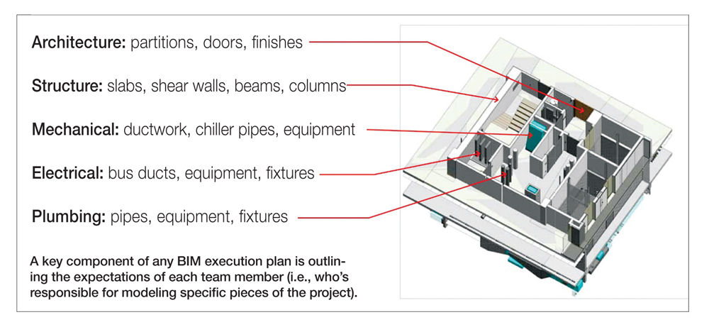
A key component of any BIM execution plan is outlining the expectations of each team member (i.e., who’s responsible for modeling specific pieces of the project).
Too often red tape gets in the way of workflow efficiency on BIM/VDC projects. For instance, some building owners hire consultants to manage the BIM process on their behalf; if not done correctly, this can result in the Building Team having to adhere to overly complicated processes and procedures.
I’ve seen BIM execution plans as long as 50 pages, with page after page of information and procedures. Some plans go so far as to point out what abbreviations the team needs to use when naming families in Revit. Is anyone really going to go to the appendix of a 50-page execution plan to look that up when they’re in the middle of modeling a family?
Another pet peeve of mine is BIM execution plans that dictate object modeling procedures. They may, for instance, require that all doors in a BIM project be modeled as simple blocks during the early stages of design and then be converted to smart objects later. That implies that the team will swap out all the doors on a project at every phase. In my opinion, it’s a complete waste of time.
I’ve found that the best way to keep BIM execution plans simple is by following these steps:
• Outline the expectations of Building Team. Have a discussion early on about which team members will be modeling which pieces of the building. For instance, the architect typically starts the structural layout, so the team needs to determine what is expected of the structural engineer and when it needs to be delivered. The architect may drive critical design elements, like slab edge locations, but I prefer that the structural engineer owns the slabs as early in the process as possible.
• Educate the client on the BIM process. Explain how the workflow differs from traditional delivery approaches. What are the schedule impacts? What are the cost impacts? After going through the process a few times, BIM only improves our workflow, and that’s a big plus for clients.
• Create a schedule of expectations. Specifically, where should the model be during the schematic design, design development, and construction document phases? Your MEP engineers will not want to develop their systems too early in the game, but it is important to understand when the major elements need to be modeled and in what phase the details are expected.
• Determine the optimal level of detail. What should be modeled? What should not be modeled? How much detail is required for each aspect of the project?
• Manage consultant grids. Everyone wants to have grids in their model, but when the architect loads five models you could end up with six of the same grid lines on top of each other. I recommend setting up a duplicate workset with the consultants’ grids so they can be turned on and off as needed.
• Establish a model sharing schedule. When conducting a coordination meeting, it is important to have the models downloaded and ready to go in advance.
• Manage the model size. Larger models need to be split up into manageable segments. For example, on a recent built-to-suit corporate headquarters project, our team split the building envelope and cores into a separate model from the interior fitout.
2. Get smart about clash detection.
Krieger and his colleagues at Gensler learned many BIM/VDC lessons while designing the 24-story Tysons Tower project in Tysons Corner, Va. Key takeaways include knowing the level of detail to incorporate in the BIM model and spotting misleading clash detection alerts.
Too often, BIM users rely on the software’s automated clash detection reports to help assess the state of a design project. The problem is that these reports grossly exaggerate the number of clashes on a project and the design team ends up wasting time clearing up hundreds of false hits.
There’s a difference between good modeling and perfect modeling. By following automated clash detection reports as the letter of the law, you can end up wasting hundreds of valuable hours cleaning up a model.
We ran into this problem with the 24-story Tysons Tower project, which is currently under construction in Tysons Corner, Va. In the BIM model, the design team inserted thousands of smart light fixtures that, when triggered, displayed a cone of light to simulate the throw of the fixture in the space.
As a result, every time a cone touched a ceiling or a wall, it would show up as a clash in the automated report. We all knew that wasn’t the case. But you could have a BIM consultant on a project who is telling the client, “Look, we have four thousand clashes and we’re going to solve them for you.” In the end, you’d just waste an enormous amount of time.
My recommendation: concentrate on the areas where you know there are going to be problems. You can’t let the computer do everything. Good architects know where they need to focus their coordination efforts.
I prefer to use the 3D capabilities of BIM to visually coordinate and manage conflicts. A standard project practice should be virtual coordination meetings, where the designers sit in a room and use the model to resolve conflicts collaboratively.
3. Put in prep time for virtual coordination meetings.
There is nothing more frustrating than having someone unfamiliar with the project or BIM software “drive” the project model during coordination meetings. It can kill the momentum of the meeting and ultimately annoy the other team members.
Let’s face it, some people simply aren’t as quick with the computer as others, and they’re slow to know which views to switch to. Not only is it painful to watch, it often leads to an inefficient meeting. At our firm, only team members who are proficient in Revit get to drive the model.
Meeting preparation is also vital. BIM models can be extremely complex, massive files. Even when using the fastest computers available, it can take 30 seconds or longer to generate a specific view in a complex model.
If you’re sitting in a room with 10 other people and there’s a question posed and everyone is throwing out ideas, invariably the room turns to silence while the model is spooling. That can kill momentum.
My teammates and I have learned that 15 or 20 minutes of prep time can go a long way toward running efficient, productive coordination meetings. You need to have views—3D views, sections, and coordination plans, all with the appropriate models loaded—set up before the meeting.
4. Apply the two-inch rule.
This is one of the first rules of designing with BIM, yet I have seen many professionals get it wrong. It goes like this: Anything in a design that is smaller than two inches in size—such as wire, conduit, and pipe—should not be modeled, because small components can usually be worked around larger components on site.
Of course, there are situations where you would want to model small components to that level. For instance, on the Tysons Tower project, we modeled the light fixtures built into the curtain wall to make sure they were designed and built properly. Doing so prevented us from creating two or three other detailed sections. We didn’t have to draw a blow-up elevation or blow-up detail; we created just one axonometric model view.
5. Get to know your subcontractors’ BIM experts.
A project’s success requires subcontractors who are well versed in both engineering and BIM/VDC tools. Otherwise, the team will end up having to spend time bringing them up to speed on the modeling process instead of working on the design and engineering.
Some consultants will tell you they are BIM experts, just to get on a proposal with you. It’s worth it to ask hard questions and even see some examples of their work.
Once you establish a firm’s credentials, find out who its top BIM expert is so you know who to call when a technology emergency arises. Don’t assume that it’s the project manager. You need to know who you can call in a bind.
6. Watch the consultants’ display backgrounds.
Just because multiple team members are referencing the same base model, you can’t assume their background views will look the same.
It is not a simple handoff, like with CAD, where the consultants take the 2D view you set up and turn it into half tones. The Revit model can have all sorts of strange display characteristics in your consultants’ models, which can lead to hiccups.
For instance, the Tysons Tower team received unnecessary comments from the plumbing plan inspector because he could not tell which direction the stairs were facing on the plumbing drawings. It turned out that the model view the plumbing engineer was using to create the plan was not displaying the architecture background properly, which led to the confusion.
There are options in BIM programs—for example, the COPY MONITOR function—where you can capture the exact view and cut plane the consultants need to use. It’s almost like a snapshot of a view that they use as a background.
Like thousands of other design and construction professionals, I’ve learned a lot about making BIM/VDC work over the last five years. My guess is this is just the start of an even longer journey.
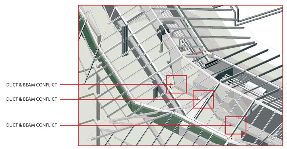
While BIM clash detection reports can be helpful in catching serious issues, like the duct and beam conflicts shown above, they tend to also list numerous false clashes. If bogus hits are not identified early on, the team could waste valuable time and resources while attempting to resolve them.
Related Stories
Museums | Aug 11, 2010
Design guidelines for museums, archives, and art storage facilities
This column diagnoses the three most common moisture challenges with museums, archives, and art storage facilities and provides design guidance on how to avoid them.
| Aug 11, 2010
Broadway-style theater headed to Kentucky
One of Kentucky's largest performing arts venues should open in 2011—that's when construction is expected to wrap up on Eastern Kentucky University's Business & Technology Center for Performing Arts. The 93,000-sf Broadway-caliber theater will seat 2,000 audience members and have a 60×24-foot stage proscenium and a fly loft.
| Aug 11, 2010
Citizenship building in Texas targets LEED Silver
The Department of Homeland Security's new U.S. Citizenship and Immigration Services facility in Irving, Texas, was designed by 4240 Architecture and developed by JDL Castle Corporation. The focal point of the two-story, 56,000-sf building is the double-height, glass-walled Ceremony Room where new citizens take the oath.
| Aug 11, 2010
Carpenters' union helping build its own headquarters
The New England Regional Council of Carpenters headquarters in Dorchester, Mass., is taking shape within a 1940s industrial building. The Building Team of ADD Inc., RDK Engineers, Suffolk Construction, and the carpenters' Joint Apprenticeship Training Committee, is giving the old facility a modern makeover by converting the existing two-story structure into a three-story, 75,000-sf, LEED-certif...
| Aug 11, 2010
Utah research facility reflects Native American architecture
A $130 million research facility is being built at University of Utah's Salt Lake City campus. The James L. Sorenson Molecular Biotechnology Building—a USTAR Innovation Center—is being designed by the Atlanta office of Lord Aeck & Sargent, in association with Salt-Lake City-based Architectural Nexus.
| Aug 11, 2010
San Bernardino health center doubles in size
Temecula, Calif.-based EDGE was awarded the contract for California State University San Bernardino's health center renovation and expansion. The two-phase, $4 million project was designed by RSK Associates, San Francisco, and includes an 11,000-sf, tilt-up concrete expansion—which doubles the size of the facility—and site and infrastructure work.
| Aug 11, 2010
Goettsch Partners wins design competition for Soochow Securities HQ in China
Chicago-based Goettsch Partners has been selected to design the Soochow Securities Headquarters, the new office and stock exchange building for Soochow Securities Co. Ltd. The 21-story, 441,300-sf project includes 344,400 sf of office space, an 86,100-sf stock exchange, classrooms, and underground parking.
| Aug 11, 2010
New hospital expands Idaho healthcare options
Ascension Group Architects, Arlington, Texas, is designing a $150 million replacement hospital for Portneuf Medical Center in Pocatello, Idaho. An existing facility will be renovated as part of the project. The new six-story, 320-000-sf complex will house 187 beds, along with an intensive care unit, a cardiovascular care unit, pediatrics, psychiatry, surgical suites, rehabilitation clinic, and ...
| Aug 11, 2010
Colonnade fixes setback problem in Brooklyn condo project
The New York firm Scarano Architects was brought in by the developers of Olive Park condominiums in the Williamsburg section of Brooklyn to bring the facility up to code after frame out was completed. The architects designed colonnades along the building's perimeter to create the 15-foot setback required by the New York City Planning Commission.


