The basic function of an air barrier system is to prevent uncontrolled air leakage through the building enclosure. An air barrier must be a complete system of materials and components that work together to provide a continuous barrier to air flow. Even small discontinuities in an air barrier can significantly reduce its performance. Air barriers must be relatively rigid or have solid backing capable of resisting moderate to high pressures caused by wind, stack effect, or mechanical pressurization of a building.
Unfortunately, the air barrier “system” concept is often ignored or not considered early enough in design. This article discusses performance criteria for air barrier systems and offers solutions to common problems found in air barrier specifications.
AIR BARRIER OR VAPOR RETARDER?
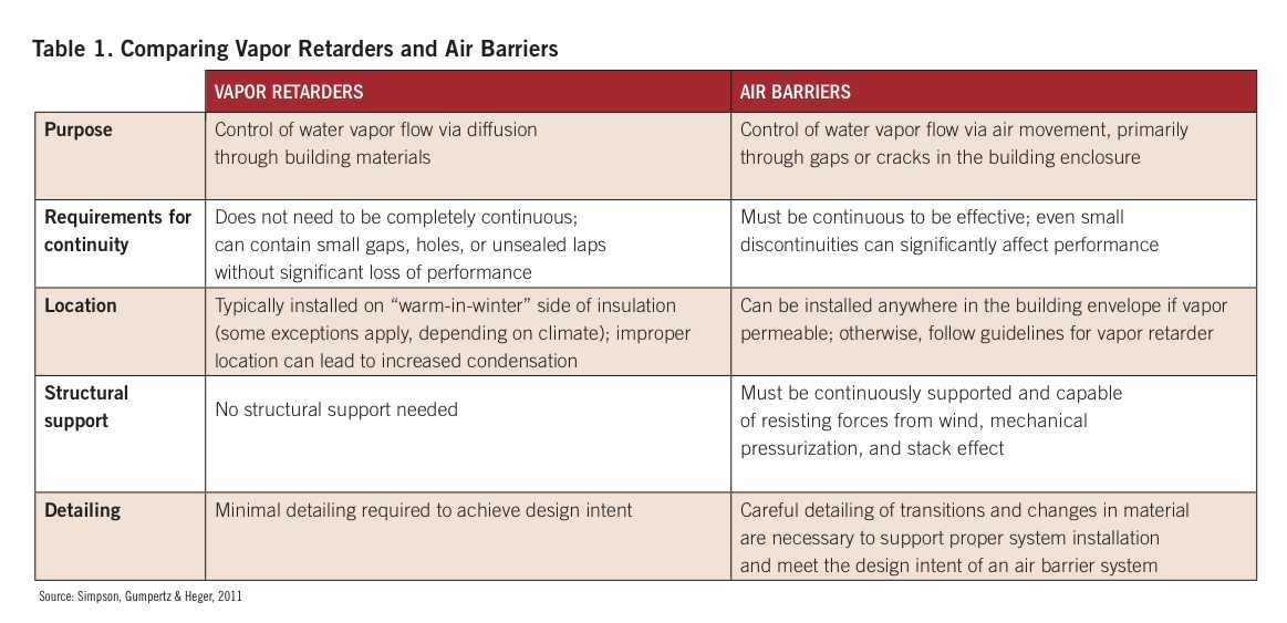
Appreciating the difference between air barriers and vapor retarders can be a stumbling block for Building Teams, especially now that many air barriers are also vapor retarders, such as the ubiquitous “peel-and-stick” membranes. The danger in confusing these two systems is that the proper location for a vapor retarder is dependent on both the interior and exterior environments, whereas an air barrier can typically be located anywhere within the building enclosure as long as it is continuous.
Table 1 summarizes the differences between air barriers and vapor retarders. Another area of confusion is the distinction between air barrier materials and air barrier assemblies and systems. An air barrier material is a primary element that provides a continuous barrier to the movement of air (e.g., self-adhered membranes). An air barrier assembly consists of the air barrier materials and accessories that provide a continuous designated plane of resistance to the movement of air through portions of building enclosure assemblies. Air barrier assemblies typically consist of both air barrier materials and connections to adjacent materials, as well as penetrations, laps, seams, etc. An air barrier system is the combination of air barrier assemblies installed to provide a continuous barrier to the movement of air through building enclosures. Specifying appropriate—and achievable—performance criteria for air barrier assemblies and systems is surprisingly difficult.
Over time, performance criteria for windows and doors, curtain walls, and roof systems have been established, and unrealistic or unverifiable performance criteria (“windows shall not leak under any condition”) have been replaced by such criteria as “windows shall not experience water leakage at a test pressure of 5.5 psf when tested according to ASTM Standard E1105.”
In contrast, performance criteria for air barrier assemblies and systems are still in development and are not often included in specifications. Air barrier systems rarely develop problems as a result of air leakage through the field of a dedicated air barrier sheet or membrane. Furthermore, air barrier products such as spray-applied or self-adhered membranes often have leakage rates that are orders of magnitude lower than the generally accepted criteria of 0.004 cfm/sf at 0.3 inches of water for air barrier materials. In short, leakage through the field of the barrier is unlikely to be a significant problem.
CURRENT AIR LEAKAGE RECOMMENDATIONS
Because most air leakage occurs at details and transitions, the air permeance of the primary air barrier materials is often only a minor portion of the air leakage through a building. The Air Barrier Association of America (ABAA, at: www.abaa.org) recommends a maximum air leakage rate of 0.04 cfm/sf at 0.3 inches of water for air barrier assemblies, which takes into account seams and penetrations and is more representative of real building conditions.
The 2005 National Building Code of Canada recommends a more conservative value of 0.02 cfm/sf at 0.3 inches of water for buildings that maintain interior relative humidity levels between 27% and 55%, which is typical of most buildings. Because even “seamless” systems, such as fluid-applied membranes, will still have transitions and penetrations, such as brick ties or other cladding attachments, applying the more stringent air barrier material criteria to air barrier assemblies is unrealistic.
The effects of air leakage through windows, doors, and curtain walls must be considered when evaluating air barrier assemblies, as much of the air leakage through a properly designed air barrier system is likely to occur through these components. Established values for air leakage through fenestration range from 0.06 cfm/sf at 1.2 inches of water for glazed curtain walls to 0.4 cfm/sf at 1.2 inches of water for operable windows.
Maximum air leakage rates are included in most building and energy codes as well as industry standards from such organizations as ASHRAE and AAMA. “Typical” values for air leakage through fenestration are somewhat difficult to determine, and building energy codes and standards have not reached a consensus. Although the test procedures for air barrier assemblies (ASTM E2357) include the air barrier connections at windows, the window opening itself is “blanked off” during the test so that only the perimeter is evaluated. Consider the example of a 10x10-foot air barrier assembly containing a 4x4-foot double-hung window.
Specifying a maximum assembly leakage rate of 0.04 cfm/sf would result in an allowable airflow of 4 cfm through the assembly. For a typical code-compliant window meeting the performance criteria of 0.4 cfm/sf, the window leakage alone would be 6.4 cfm, exceeding the allowable value for the entire assembly without even considering leakage through other air barrier components. If a window is specified in assembly testing, a modified value for assembly leakage that considers the inherently “leakier” windows must be used.
To account for the wide range of materials, details, and transitions in the air barrier of any particular building, it is often more useful to speak in terms of system (i.e., whole building) air leakage than material, assembly, or component leakage. This is especially true for purposes of energy simulation or HVAC load calculation, where the global quantity of air leakage is the primary concern. Unfortunately, there are few established standards for whole building air leakage that designers can reference.
The 2009 ASHRAE Handbook of Fundamentals notes three “levels” of air leakage for typical buildings: 0.1 cfm/sf at 0.3 inches water for “tight” buildings, 0.3 cfm/sf for “average” buildings, and 0.6 cfm/sf for “leaky” buildings. These general classes of air leakage were first presented in the results of a study of eight commercial buildings in Canada, ranging in height from 11 to 22 stories and clad with glazed aluminum curtain walls. Despite being based on a small sample size and very specific building types, these “classes” are frequently cited in discussions of typical building airtightness or building performance criteria.
U.S. STUDY SHOWS SIGNIFICANT LEAKAGE
A more recent study of some 200 low-rise commercial and institutional buildings in the U.S. found an overall average leakage rate of 1.55 cfm/sf at 0.3 inches of water—more than five times greater than the average value of 0.3 cfm/sf noted above. Unfortunately, neither study makes it clear if the buildings were designed with continuous air barriers. Considering this limitation, the average value of 1.55 cfm/sf from the 2005 study could be seen as a maximum value for building air leakage, as a new building with a dedicated, continuous air barrier is likely to provide greatly improved performance.
While the ABAA recommends an overall building air leakage rate of 0.4 cfm/sf at 0.3 in. of water, the U.S. Army Corps of Engineers specifies a leakage rate of 0.25 cfm/sf at 0.3 inches of water. In 2002, the United Kingdom added a requirement for whole building/system air leakage to its “Building Regulations for England & Wales” for commercial buildings greater than 10,760 sf. The established value, which is required to be verified through whole building testing, is 0.547 cfm/sf at 0.2 inches of water. Preliminary findings have shown a marked improvement in airtightness of more “standardized” building types such as warehouses and retail stores, with many buildings exceeding the code-required value. This is a significant improvement, as typical values for air permeability of the same building types prior to the 2002 code change were on the order of two to three times higher than values achieved in recent years.
However, less standardized building types, such as offices, schools, and hospitals, have exhibited a much lower “passing” rate. This is most likely attributed to the general lack of attention to air barrier detailing at conditions for which typical practices are not well established, in contrast to less unique building types for which a large body of detailing experience exists. Given the results of recent studies in the U.S., the average commercial building significantly exceeds this target. Until additional studies of more recently constructed buildings (designed with continuous air barriers) are available, system air leakage criteria may be difficult to enforce due to the lack of knowledge about what level of air leakage is typical and achievable for new buildings. Moreover, the acceptability of leakage criteria is likely to fluctuate as new data becomes available and more testing is performed.
SPECIFYING AIR BARRIER SYSTEMS
Currently, there is a significant disconnect between the criteria contained in most specifications for air barrier system and the actual performance in the field. This is due to a combination of factors, including designers’ unfamiliarity with air barrier systems, poor understanding of how air barriers function, and misunderstanding regarding test procedures and limitations.
The ABAA has proposed a new specification section to establish the administrative and procedural requirements necessary for the construction of a complete air barrier system in a new building. Because the air barrier system consists of multiple materials covered under several specification sections (including windows, doors, curtain walls, roofing systems, and exterior wall air barriers), this specification seeks to establish some kind of connection between the various sections and provide a means of coordinating the different trades involved in the construction of the air barrier system. Individual designers have also developed standard specifications for their own projects.
As the popularity of air barriers has grown in the past few years, so too have the number of projects where air barriers were added to the scope during design (or even early construction) by the inclusion of a single specification section for a sheet or spray-applied membrane. This approach creates an air barrier in name only, and does not address the numerous connections of that material/assembly to other components in the building. Details such as window perimeters and roof-to-wall joints are critical to the performance of the overall air barrier system, and require much more coordination and planning than is likely to happen during the construction process, when trades may be running behind schedule and design/consulting budgets may have been exhausted. BD+C
How to Avoid Common MistakesWhen Specifying Air Barrier Systems Properly coordinate all air barrier components.
Don’t make the mistake of specifying windows that are difficult to integrate successfully with the air barrier, or specifying air barrier materials or assemblies with conflicting performance criteria. The air barrier is only as strong as its weakest component, so specifying high-performance windows in a building with a poor air barrier (or none at all) will do little for overall airtightness.
The same is true of specifying an air barrier in a wall but not in the adjacent roof, while requiring the entire building to pass an airtightness test. Quantitative testing of air barrier systems installed as part of a building addition where the “base” building has no such systems is also generally of little value, unless the addition is separated by airtight interior partitions to make it a truly separate volume.
Provide sufficient details for the air barrier system, especially at critical junctures such as window perimeters and roof-to-wall interfaces. Many specifications provide only general information or insufficient detail on the drawings, but may include language intended to place the detailing design burden on the contractor. Air barrier systems are complex and require careful design to be effective. It is unreasonable to expect contractors to assume the role of primary designer of the air barrier details.
Don’t specify impossible or unrealistic test criteria. Some specifications require that air barrier assemblies be tested in the field to verify performance, but do not take into account the many uncertainties associated with qualitative testing that may make testing impractical or unlikely to yield useful results. Some specifications contain incompatible test criteria, such as including a window in the air barrier assembly that is tested but not adjusting the assembly criteria to account for the inclusion of that window. Given the differences between criteria for windows and criteria for air barrier assemblies, it may be impossible to meet the “typical” assembly leakage of 0.04 cfm/sf due to leakage at the window.
Don’t specify system performance criteria that are not backed up by research or practical experience. Given the lack of whole building airtightness data on recent buildings that include air barrier systems, specifying a system leakage rate can lead to confusion or disagreement if the building fails to achieve the test criteria. Without realistic established values for system leakage, it may be difficult to enforce compliance with such a requirement.
Read the five-part series, “Air Barrier Systems,” at www.bdcnetwork.com/article/air-barrier-systems.
Sean O’Brien is an Associate Principal and a specialist in building science and building envelope performance in the New York City office of national engineering firm Simpson Gumpertz & Heger. Michael Waite is a Senior Building Technology Engineer in SGH’s New York office. He specializes in building envelope energy performance and is a member of ASHRAE SSPC 90.1 and its Envelope Subcommittee.
Related Stories
| Oct 7, 2011
GREENBUILD 2011: Transparent concrete makes its North American debut at Greenbuild
The panels allow interior lights to filter through, from inside.
| Oct 6, 2011
GREENBUILD 2011: Dow Corning features new silicone weather barrier sealant
Modular Design Architecture >Dow Corning 758 sealant used in GreenZone modular high-performance medical facility.
| Oct 4, 2011
GREENBUILD 2011
Click here for the latest news and products from Greenbuild 2011, Oct. 4-7, in Toronto.
| Oct 4, 2011
GREENBUILD 2011: Nearly seamless highly insulated glass curtain-wall system introduced
Low insulation value reflects value of entire curtain-wall system.
| Oct 3, 2011
Balance bunker and Phase III projects breaks ground at Mitsubishi Plant in Georgia
The facility, a modification of similar facilities used by Mitsubishi Heavy Industries, Inc. (MHI) in Japan, was designed by a joint design team of engineers and architects from The Austin Company of Cleveland, Ohio, MPSA and MHI.
| Sep 12, 2011
Living Buildings: Are AEC Firms up to the Challenge?
Modular Architecture > You’ve done a LEED Gold or two, maybe even a LEED Platinum. But are you and your firm ready to take on the Living Building Challenge? Think twice before you say yes.
| Jul 22, 2011
Five award-winning modular innovations
The Modular Building Institute's 2011 Awards of Distinction highlight fresh ideas in manufactured construction projects.
| Oct 13, 2010
Community college plans new campus building
Construction is moving along on Hudson County Community College’s North Hudson Campus Center in Union City, N.J. The seven-story, 92,000-sf building will be the first higher education facility in the city.


